Installing the C-Mount-Retrofitted Global Operating Microscope Camera Adapter
Richard J Kinchhttp://www.truetex.com/
Revised: April, 2015
Kit contents:
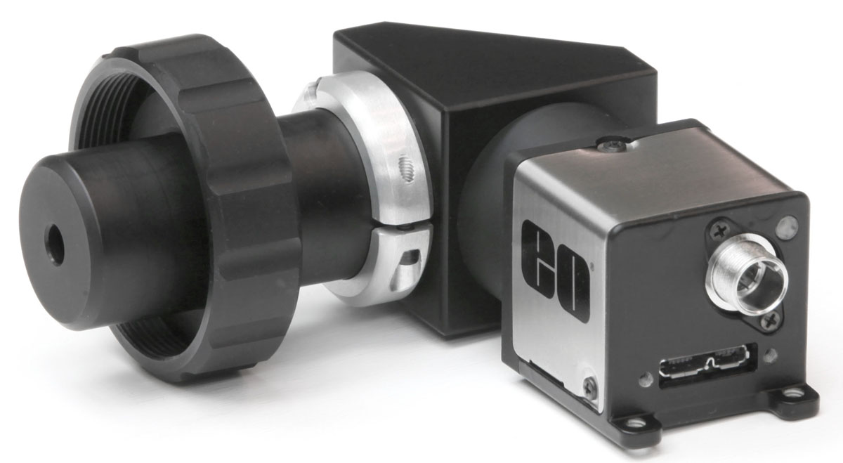
• Modified Global adapter with newly retrofitted C-mount fitting.
• C-mount camera (if purchased with the kit or otherwise provided to us).
• 2mm and 0.050-inch hex key tools.
• Printed copy of these instructions. Read online at http://www.truetex.com/global_operating_microscope_c-mount.htm.
The following procedures are required to obtain proper function of the adapter on a particular instrument configuration. The process is technically intricate and complex, due to the flexibiility of the adapter in three independent factors: the angle of the adapter orientation on the instrument, the angle of the camera rotation on the adapter, and the calibration of the precise focus of the camera to the binocular visual focus (termed "parfocality"). Hence you must adjust each of these factors one at a time using the following steps.
Attaching the C-mount camera to the adapter: Screw the camera's C-mount threaded receptacle onto the C-mount threaded fitting on the adapter diagonal. The camera will seat against the flat face of the diagonal. Tighten gently, just enough that the camera does not come loose in normal use, but not so tight as to stress the camera or fitting. When seated, the camera will stop at a random rotation and likely not be aligned properly, but ignore any rotational misalignment for now and adjust it in the last step below.
Attaching the adapter to the microscope: Insert the adapter fitting into the microscope's beamsplitter receptacle, rotate the adapter on the receptacle axis for your choice of orientation, and tighten the lockring. Choose an orientation (typically in 90 degree increments from the microscope's optical axis) which places the adapter and camera in a convenient position to not interfere with your microscopic work activity; normally this is vertically upwards and away from the microscopic subject, but special applications or interference with other accessories on the instrument may require the option of a horizontal or even downwards orientation of the adapter and camera. (The 90-degree increment is not required, so you can choose any convenient angle, although this requires a compensating adjustment of the camera rotation as a last step in the installation process.)
Activating the camera: Turn the camera on and obtain a live video image. How this is done depends on the type of camera you are using, and the computer or display that you are using with the camera, and is not covered by these instructions. The live image may be rotated or out of focus at this point, which you may adjust in the following steps.
Setting up a test view: Set up a test view by placing a suitable target (something flat like a business card) in the microscope's field of view. Adjust the diopter settings of the eyepieces for your eyesight, and focus the target visually in the binoculars of the microscope. Ignore any rotational misalignment of the camera image for now while you adjust the focus. The goal of this step is to calibrate the camera to be "parfocal" with respect to the binocular view, so it is critical that you use the proper technique of diopter settings and relaxed accommodation to focus the microscope visually before adjusting the camera focus. This is particularly critical if the microscope provides a zoom or magnification-change feature (as most do), since miscalibration of parfocality will result in loss of focus when changing magnification.
Adjusting focus: Normally the camera focus will be adjusted for a C-mount standard camera when you receive the adapter, but some cameras are not themselves quite precisely standard and may require a focus adjustment. You may adjust the camera focus by loosening the collar clamp, and then turning the adapter fitting in or out of its threaded attachment to the diagonal as follows. First, use the 2mm hex key to loosen the one cap screw on the collar which acts as a clamp onto the adapter fitting tube. (Do not loosen the other two cap screws which attach the clamp to the diagonal.) Second, turn the diagonal with respect to the adapter fitting to move the focus in or out while watching the live video display. This turning action will feel somewhat stiff as it rubs against the loosened collar, but should not require forcing the action. If the camera only provides still photos and not live video, you will have to make slight focus adjustments while taking photos in a stepwise procedure to detect the proper focus. Once you obtain a proper focus, tighten the cap screw to lock the adjustment.
Adjusting the rotation of the camera view: If the camera is not rotationally aligned for an upright image (likely if we did not have your camera to perform this adjustment after retrofitting your adapter), adjust the rotational alignment as follows. If the camera itself happens to provide a rotational adjustment (most do not), use that feature. If not, you will have to apply the following adapter adjustment, which is rather intricate. The goal is to have the camera seat onto the diagonal face with the proper angle for an upright view. The rotational alignment mechanism is demanding of technical skill and care, but a successful adjustment provides a stable and compact assembly. (The constraints of the original adapter design do not allow for a simpler mechanism within the constraints of the C-mount mechanism.)
Remove the camera from the adapter by unscrewing it from the C-mount fitting on the diagonal. While you are starting to unscrew the camera for the first turn, observe the live video display and determine the proper 90-degree angle of the camera on the adapter to yield a properly upright image for the adapter orientation you have chosen. The camera will go out of focus while you unscrew it from the adapter, but the first few turns will retain enough focus for you to make this target angle determination. Observe the threaded fitting, which projects approximately 4mm from the diagonal face. Observe the three tiny set screws placed radially in the threaded face of the C-mount fitting. These set screws are very tiny and may require magnification to see properly (but then you have a splendid microscope at hand to inspect them!). Ignore any extra holes in the C-mount fitting which do not contain set screws (these are involved in the part fabrication). Use the 0.050-inch hex key to loosen the set screws (about one full turn), and observe that you can now spin the C-mount threaded fitting loosely around the optical axis. The task is to estimate the amount of spin to bring the seated camera to the desired angle for an upright view. Tighten the set screws gently, and replace the camera on the C-mount fitting, and estimate how much the seated angle is away from the upright goal. Remove the camera again, loosen the set screws again, turn the C-mount threaded fitting by the estimate, tighten the set screws again, and replace the camera against the diagonal face. Repeat this trial-and-error adjustment (tediously, perhaps) until you achieve the goal of an upright image with the camera seated against the diagonal face.