A Mattock Tool for Moving Heavy Machinery by Hand
 This improvised, shop-made tool is a specialized lever for prying heavy machinery up from the floor,
such as when moving the 2400-lb Bridgeport milling machine.
This allows you to lift such a machine enough to get pieces of 3/4" pipe (as hard rollers) underneath for
the "Egyptian pyramid construction" method of moving.
You can also nudge the machine directly on the floor to make small adjustments to its position,
or lift an edge to slip shims or wedges underneath for leveling.
This improvised, shop-made tool is a specialized lever for prying heavy machinery up from the floor,
such as when moving the 2400-lb Bridgeport milling machine.
This allows you to lift such a machine enough to get pieces of 3/4" pipe (as hard rollers) underneath for
the "Egyptian pyramid construction" method of moving.
You can also nudge the machine directly on the floor to make small adjustments to its position,
or lift an edge to slip shims or wedges underneath for leveling.
The mattock is welded from small scraps of 1018 hot-rolled steel (found at a local steel supplier).
Before making this design, I had tried several earlier designs using steel pipe, but found that they were too weak
for the extreme forces involved in prying masses of this size.
This welded arrangement of three solid pieces is about the lightest which will do the job without breaking welds
or bending the components.
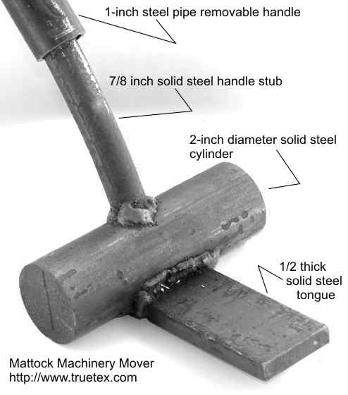
At the top left you see the end of a piece of 1-inch schedule 80 steel pipe, which is a
long removable handle which simply slips loosely over the welded-on handle stub.
I use about a 5-foot length of pipe, which provides enough leverage to easily lift a heavy item,
but without being unwieldly, and without being "springy".
 The main steel cylinder is 2 inches in diameter and 6 inches long.
Into this cylinder, I milled a 1/2-inch deep by 2-inches wide tangential slot to receive a tangentially oriented "tongue".
The tongue is a scrap of 1/2-inch thick steel, 2 by 5 inches.
This is designed to fit the base of a Bridgeport milling machine, which
has recesses to admit the point of a lever of this thickness and width.
The main steel cylinder is 2 inches in diameter and 6 inches long.
Into this cylinder, I milled a 1/2-inch deep by 2-inches wide tangential slot to receive a tangentially oriented "tongue".
The tongue is a scrap of 1/2-inch thick steel, 2 by 5 inches.
This is designed to fit the base of a Bridgeport milling machine, which
has recesses to admit the point of a lever of this thickness and width.
Radially projecting at an angle is the handle stub, which is a 7/8 inch solid bar
about 8 inches long, and set into a 1/2 inch deep 7/8 inch diameter hole
in the main cylinder.
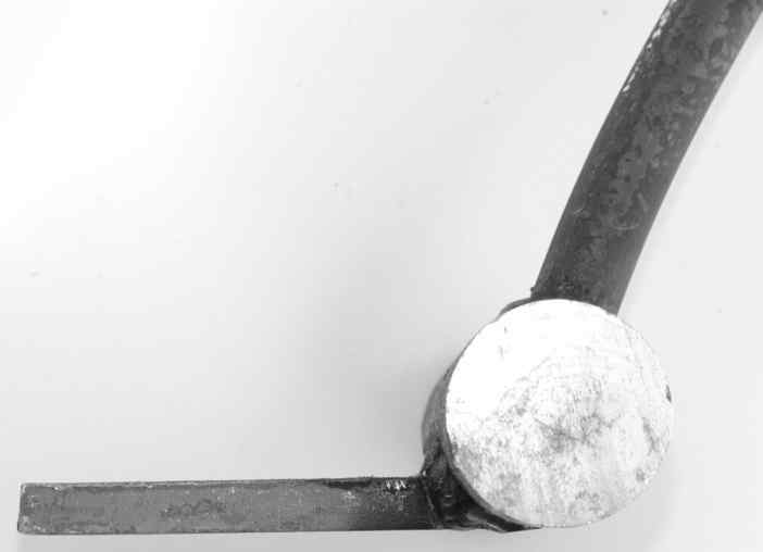
The welds (yes, a bit sloppy) were made with ordinary L-56 steel wire with a small MIG welder,
and were ground flush with an angle grinder on the bottom rounded surface.
The welded assembly (without the pipe handle) weighs 8 lbs.
The angle of the handle stub is set to have the long pipe handle tilt somewhat away from the
object being moved, so as to clear the sides and allow various approaches.
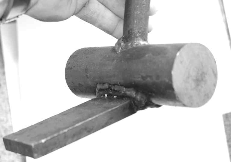 The tangential weld of the tongue onto the cylinder, the large diameter of the cylinder, and the
smoothly ground welds on the bottom, all serve to
spread the force of the lifting evenly across enough area to prevent fracturing and crumbling a concrete floor.
If your tool concentrates the forces improperly, you end up with a damaged floor.
The smooth cylinder serves as a wide bearing area to spread out the force of the leverage, as the
lever is tipped back.
The tangential weld of the tongue onto the cylinder, the large diameter of the cylinder, and the
smoothly ground welds on the bottom, all serve to
spread the force of the lifting evenly across enough area to prevent fracturing and crumbling a concrete floor.
If your tool concentrates the forces improperly, you end up with a damaged floor.
The smooth cylinder serves as a wide bearing area to spread out the force of the leverage, as the
lever is tipped back.
To further cushion the floor from damage, you can insert a hard plastic shim under the rolling portion of the
mattock. Sides of old polyethylene buckets can be cut up into sheets for this purpose.
Lately I've noticed the handle stub has started to bend just slightly after some use (as may be noticeable
in the photos), so this component should be stepped up a bit to 1-inch diameter or more, and the pipe handle
enlarged accordingly. This is the design shown in the drawings below.
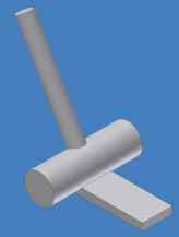 You can inspect a 3D solid model [Autodesk DWF file, 5 KB].
(This requires the free Autodesk DWF Viewer).
The viewer allows you to rotate ("orbit"), pan and zoom the 3D model.
You can inspect a 3D solid model [Autodesk DWF file, 5 KB].
(This requires the free Autodesk DWF Viewer).
The viewer allows you to rotate ("orbit"), pan and zoom the 3D model.
You can also view the dimensioned mechanical drawing [PDF file, 16KB].
|
Have a comment or question about my mattock machinery mover?
Email me at:
kinch@truetex.com
Richard J. Kinch
Back to Machine Shop page
Back to Home page