

August, 2006 -- March, 2013.
Spherometers are small precision instruments for measuring the radius of curvature of spherical surfaces. The term may also be spelled as a "spheremeter" or "sphereometer". The most common application of a spherometer is the measurement of an unknown lens shape, in order to study its optical characteristics. This is the application I had in mind in designing these instruments, and they are scaled in size accordingly.
While spherometers have been around for centuries, and are commercially available today (surplusshed.com specimen, search eBay) my designs are novel in that they are fixtures which work with standard digital calipers and a flatness reference, instead of the usual design which incorporates a micrometer. Thus they are easily made in the machine shop, and need not be fabricated in high precision, but still produce precise measurements. Since an optics laboratory is likely to be equipped with calipers and flats already, the addition of a spherometer may be nearly free.
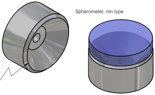
The principle of metrology in the spherometer is simple: the tips of 3 legs, or the rim of a conical projection, are held in a fixed plane and rested on the subject surface. The chordal distance from the center of these sample points to the surface is measured, and by geometry the radius of the sphere is known from the chordal distance and leg space or rim diameter.
See the CAD models and drawings (223 KB PDF file). The drawings should be sufficient for a machinist to fabricate the complete assembly.
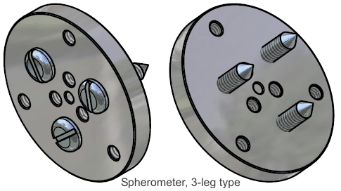
The rim type spherometer is cut from aluminum, steel, or brass with a single fixturing procedure on a lathe. This design suffers from over-constraint in the sense of kinematic design principles, but it is easier to make. In contrast, the 3-leg sphereometer is kinematically sound, and with proper calibration is capable of the best precision attainable in this type of instrument.
The 3-leg type is likewise made from metal, and requires drilling and tapping holes which should be located precisely as possible in a piece of metal plate, The metal plate need not be any particular shape, such as the disc shown in the drawings, as long as the holes are properly placed. These holes could be placed directly with a milling machine, or with a drill press by first scribing and center-punching the centers. The 3-leg screws can be accurately pointed in a lathe, but this could also be roughly improvised by hand filing. In principle the 3-leg spherometer fixture could be made with nothing but hand tools.
You can correct any inaccurate hole placement or screw symmetry by precisely measuring the screw tip spacing (such as by using the calipers) and adjusting radius in the formula accordingly. Or, you can measure a surface of known precise curvature, and invert the formula to learn the effective 3-leg radius.
The calipers required are of the standard digital type (inexpensive example) which measure to a precision of about 0.01mm. The flatness reference can be any hard, precisely flat item, such as an optical flat, a granite surface plate (inexpensive example), metalworking gage block, machine tool table or way, etc.
To calibrate (zero) the spherometer, you place the 3-legs (or rim of the cone in the cone type) onto the flatness reference. Insert the depth probe of the calipers through the center hole of the fixture, as if to measure the depth from the top of the fixture to the reference surface, and push the "zero" button to set the digital calipers to read zero at that depth. You can also zero to a lens of known precision curvature, and add the corresponding depth to subsequent measurements.
To measure a convex curvature, you probe the depth again with the digital calipers, this time to the subject lens surface from the top of the fixture, and record this distance. The radius of curvature is then R = r^2/2h + h/2, where r is the radius of the bolt circle (tips of the screws in the 3-leg design, or radius of the rim in the round type), and h is the depth measurement.
The bolt-circle diameter on the 3-leg spherometer is adjustable between 3 selections of 15mm, 30mm, or 50mm. To change the diameter, you simply remove the screws from one set of holes and insert them in the other. For best accuracy, you should use the largest diameter that is still smaller than the lens being measured. I chose 50mm as the largest size because that is about the largest diameter of lenses I work with. The design scales proportionately to larger sizes if needed.
Measuring a concave curvature is similar, except you may need to manipulate a small precision ball bearing of known diameter between the caliper depth probe and the surface under test (having likewise zeroed the calipers to the ball bearing against the flatness reference).
The instrument also allows quick comparisons of lenses by setting the curvature depth of one lens to zero on the calipers, and then probing other lenses.