PROCEDURE:
Canon CF-60U retrofit
Richard J Kinch
https://www.truetex.com/
February, 2010
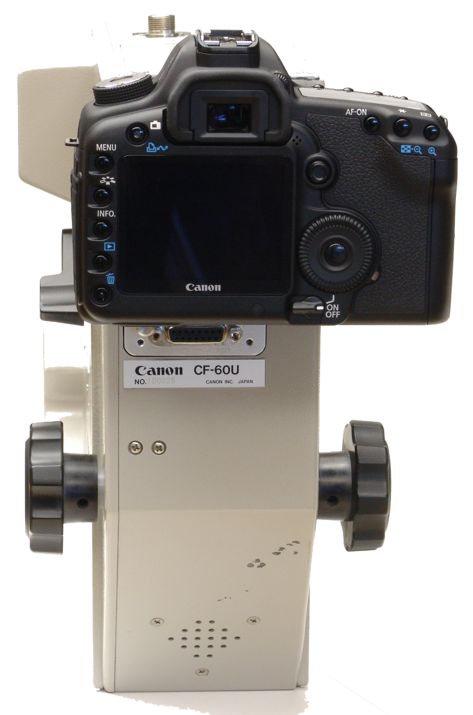
This procedure retrofits the Canon CF-60U retinal camera to use a digital SLR camera such as the
Canon 5D Mark II instead of the original Canon F-A 35mm film camera. Only the installation is described here;
operation of the upgraded unit is described elsewhere.
Left and right are understood from the operator's normal point of view.
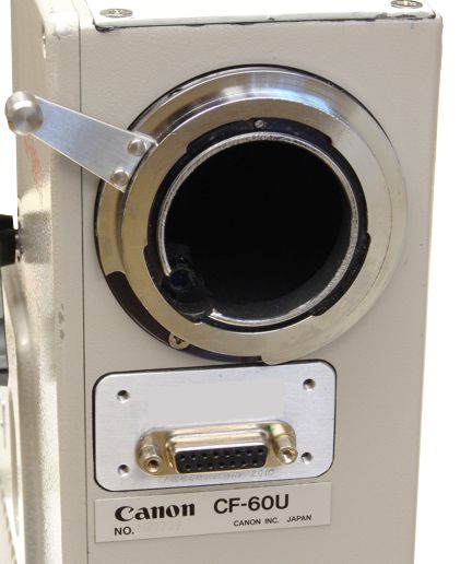
"Park bench" refers to the pogo pin connector below the bayonet on the rear of the instrument.
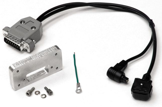
KIT CONTENTS
- One custom rear-port bulkhead bracket
- One D-sub 15-pin female solder-cup connector
- Two D-sub hex standoff screws with lock washers
- One 2-inch stranded, insulated wire ground jumper, one end stripped/tinned, one end with 1/8-inch eyelet
- One D-sub 15-pin male connector with hood and custom interface circuitry, hot-shoe cable, and Canon N3 remote cable.
- One of either (1) non-parfocal bayonet adapter ring, Canon EF mount to Canon CF-60U, or (2) replacement parfocal bayonet assembly for Canon EF mount.
- Small cables ties for temporary use during installation, and for permanent installation for wire management.
DISASSEMBLY
- Turn off the unit and disconnect from power.
- Remove angle and focus knobs on left side, by loosening two setscrews (at 90 degrees) on each knob with 2mm hex key.
- Remove left cover screws (five M3-10 Phillips) and the cover itself.
Leave the ridged lamphouse cover in place; do not remove it or its screws.
- Remove the last data mirror located on a bracket (2 M3-4 black Phillips screws) just before bayonet.
- Remove last data mirror support bracket (2 M3-4 black Phillips screws).
This exposes 4 cap screws holding the park bench.
- Remove screws (four M3-8 SHCS black, 2.5mm hex key) holding park bench from inside. Bend light shield
and wires above slightly to access.
A short ball-head hex key and forceps help manipulate these screws in the tight space.
Retain screws for later reuse.
- Remove black Phillips screw holding small brown PC board (connected to park bench) on chassis, and the
small Phillips screw.
- Remove screws (three M2-5) holding green PC board to chassis.
- Wires to park bench should now have slack for modification.
- Cut 8 wires leading to the park bench (6 to pogo pins and 2 to switch). Cut as close to the park bench as possible.
- Remove park bench, which is now surplus.
- Move loose wires into chassis and out the side to provide slack for soldering.
- If you are also replacing the rear-port bayonet assembly with the parfocal replacement as part of the upgrade,
then remove the old bayonet assembly now (see annotated photo below).
INSTALLATION
- Prepare DB-15F connector (female 15-pin D-sub) and bulkhead plate per drawing (canon_cf-60u.idw).
- Place bulkhead plate over 8 wires and temporarily secure with cable tie, leaving as much wire slack as possible.
- Strip, tin, and solder 8 old wires to DB-15F per wiring chart:
- 1 GRN
- 2 BLU
- 3 BLK
- 4 YEL (not switch)
- 5 ORG
- 6 WHT
- 7 YEL (switch)
- 8 BRN (switch)
- 15 (jumper to chassis screw)
- Remove temporary cable tie.
- Attach DB-15F to bulkhead plate with hex standoff screws and lockwashers.
Do not overtighten the hex standoffs or use thread locker, as the screw shoulders are easily twisted off.
- Feed DB-15F and bulkhead plate through chassis port, dress wires as appropriate with cable tie(s), and secure the
bulkhead plate with M3-8 SHCS cap screws (2.5mm hex key) removed previously from park bench.
- Plug the electronic interface cable male connector into the female receptacle, and engage and tighten the screws.
- If the kit includes the parfocal Canon EF rear-port attachment, replace the old camera attachment as follows:
- Remove the stop screw at the 6 o'clock position which limits the bayonet lock ring rotation.
- Rotate the bayonet lock ring clockwise to remove it. Remove the handle if needed to clear the rotation.
- Remove the screws fastening the old bayonet base to the instrument upper unit frame.
- Install the new Canon EF rear-port attachment assembly with the screws just removed.
- Install the digital SLR camera on the new parfocal bayonet if so equipped, or with the non-parfocal bayonet
adapter ring if using the original bayonet receptacle.
- Connect the hot-shoe and shutter-remote cables from the electronic interface to the digital SLR.
Reassembly
The remaining reassembly is the reverse of the disassembly.
Once the instrument is reassembled, you may proceed to configure the digital SLR and original instrument
for digital retinal photography, as described elsewhere.


Copyright 2010 Richard J Kinch


