INSTALLING AND OPERATING THE
DIGITAL CAMERA ADAPTER FOR THE
TOPCON SL-2D SLIT LAMP BEAMSPLITTER
Richard J Kinch
http://www.truetex.com/
Revised: April, 2011
Description and contents:
The digital camera adapter for the Topcon SL-2D slit lamp provides
an attachment and optical interface for a standard digital SLR camera.
The kit contains the following items:
- Main adapter assembly (beamsplitter fitting, diagonal body, SLR camera bayonet fitting, dust cap).
- Setscrew (M4x0.7-4) and hex key (2mm) to optionally replace the adapter thumbscrew
for locking a semi-permanent orientation.
- A printed copy of these instructions.
Compatible instruments:
This adapter works with the Topcon slit lamp beamsplitter which is an option for the Topcon SL-2D slit lamp.
This same Topcon beamsplitter also fits Topcon slit lamp models SL-2E, SL-5D, and SL-6E, and the Topcon OMS-70 operating microscope.
For the Topcon models SL-5D and SL-6E, which provided a built-in beamsplitter and 35mm film camera coupler, better photographic performance is
obtained by upgrading the coupler for a digital SLR camera, which we provide in a different adapter product described at
http://www.truetex.com/range.htm.
Compatible cameras:
Virtually all makes and models of digital SLR cameras are compatible with this adapter.
Our standard configuration is for the Canon EF lens mount which is used on all current Canon SLR cameras.
Any model Canon SLR camera body is thus compatible with this configuration of the adapter.
We also optionally configure the adapter for other SLR makes such as Nikon, Olympus, Sony, etc.
Suggested less-expensive camera models are the Canon Rebel T2i, T3i, or XS.
Models such as the Canon T2i will also provide live HD video via a HDMI connector which you can connect to a standard HDTV.
These perform well with the adapter and are all that is needed for slit lamp photography.
If you expect to use the camera for conventional photography off the slit lamp instrument, consider
the mid-range Canon line, such as the Canon 60D or 7D, which provide sturdier construction and a much better viewfinder.
High-end models like the Canon 5D Mark II are compatible but will outcrop the image.
Any model camera body, including the least expensive, outperforms the theoretical resolution of the Topcon
instrument, so additional camera resolution will not improve the photographic quality.
Installing the adapter:
- Observe and identify the components of your Topcon instrument and the digital camera adapter.
See Photos 1 through 3 below.
- Remove the beamsplitter fitting from the adapter by loosening the thumbscrew.
This fitting is the 2-inch diameter aluminum piece held by the thumbscrew.
See Photo 6 below.
Take care not to touch the lens in the fitting.
-
Choose a port on the beamsplitter to receive the adapter; normally this is the port on the right side from the observer's
point of view. Unscrew the dust cap from the chosen beamsplitter port, if present.
-
Screw the beamsplitter fitting onto the beamsplitter port.
Take care when engaging the threads, as they are fine and delicate.
Hand-tighten the fitting only, but tighten enough that the fitting will not come
loose when the weight of the adapter and camera are added.
-
Attach the Topcon beamsplitter (with adapter beamsplitter fitting) and Topcon binocular to the Topcon instrument,
using the threaded rings.
-
Choose an orientation for the camera and adapter.
See Photo 2 (normal orientation) and Photo 3 (alternate orientation) below.
Photos 4 and 5 give different views of the normal orientation.
-
Attach the digital SLR camera body to the adapter bayonet fitting.
Use a small screwdriver to loosen the three setscrews in the bayonet fitting, so you can rotate the fitting
and obtain the chosen orientation of the camera.
Rotating the fitting may also be necessary to clear the camera's protruding flash "nose" around the diagonal body.
Secure the proper orientation of the camera body by tightening the bayonet fitting setscrews.
The threaded adapter ring between the bayonet fitting and the diagonal body may also turn, in which case you must
use the setscrew adjustment to tighten the fitting to the body while stopping at the proper orientation.
The bayonet should be firmly attached to the diagonal.
There is normally a slight rotational play of the camera body on the bayonet fitting, which is not a concern.
-
Slide the camera with attached adapter over the beamsplitter fitting.
Engage the fitting into the adapter with about 6mm (1/4 inch) of the fitting projecting from the adapter sleeve.
See Photos 7 and 8 below.
Turn and hold the assembly into the proper orientation, and lock this position by tightening the adapter thumbscrew.
-
While you are now ready to take photographs, they will not likely be properly focused until you perform
the parfocal calibration described in the following section.
-
Yet another technique for calibrating focus is to remove the assembled beamsplitter, adapter, and digital camera from
the instrument, and focus the camera's view through the beamsplitter at infinity. This is most precisely done
by viewing the 10X live view on the camera, if so equipped. View a bright daylight scene, such as a distant
landscape, as an infinity target. The magnification of the camera is such that this will require mounting the
camera temporarily on a tripod to obtain a steady image for focus calibration.
-
Once you have established the proper focus calibration
you may wish to mark or scribe a line on the beamsplitter fitting against the shoulder of the diagonal sleeve, indicating the
proper insertion for parfocality. Then you can return the adapter to parfocality by using this mark, instead of having
to repeat the calibration process, if it should be necessary to rotate the adapter again.
Calibrating parfocality of the camera to the instrument binocular:
- Obtaining properly focused photographs in the camera requires that you calibrate the focus of the camera to equal the focus of the
observer's view in the eyepieces. This goal of equal focus is called "parfocality".
You need only perform this calibration when first installing the adapter or changing the adapter orientation.
Follow the steps immediately below.
-
Obtain a properly focused view in the instrument.
The best way to do this is to view the calibration rod which inserts into the slit lamp pivot, which guarantees a focused target.
This rod was provided by Topcon originally with the instrument.
-
If the Topcon calibration rod is not available, then you will have to use an eyepiece view of an improvised test target.
Stretch a piece of tape holding a test target
(such as a business card) between the upright posts of the instrument headrest, at the level of the canthus marks.
Move the instrument carriage to focus the instrument on the test target as viewed through the eyepieces.
Use the carriage lock to fix the instrument on this focused view of the test target.
In focusing with the eyepieces, it is critical that you use the eyepiece diopter correction to compensate for any
ametropia in the observer's eyesight. Use the crosshairs visible in the Topcon eyepiece(s) to confirm this compensation.
See the Topcon slit lamp documentation for details. If you do not perform this compensation,
the focus calibration will incorrectly include the observer's refraction error.
-
Obtain a live view image of the microscopic scene on the digital camera display.
If your digital camera does not provide a live view feature, you will instead have to use the camera's optical viewfinder.
If using the optical viewfinder, apply any diopter correction needed for ametropia as explained in the camera documentation.
-
While holding the camera and adapter, loosen the thumbscrew on the adapter sleeve.
Slide the beamsplitter fitting in and out of the adapter sleeve while observing the live view (or viewfinder).
Hold the position in this sliding range which brings the camera image into focus, and lock the position
by tightening the thumbscrew.
-
Return to the binocular eyepiece view on the instrument, and confirm that the test target is still in focus and has not moved.
-
If you focus the subject using the camera's live view, parfocal calibration is not required.
With the camera live view, you preview the exact focus of the camera image.
Indeed, you may obtain the most precise focusing by viewing the 10x live view on the camera display or external monitor.
Certain older or less-expensive camera models do not provide a live view feature, however.
Taking photographs:
-
Digital SLR cameras themselves are complex devices, so you may wish to study the manufacturer's manual for the camera
to understand the appropriate settings and procedures.
-
The slit lamp effectively becomes a manual lens for the digital SLR camera.
-
For slit lamp photography, set the camera's mode dial to "Av" (aperture priority) or "M" (manual shutter speed).
Control the exposure by setting the lighting available
the camera's ISO speed setting, and the camera's exposure time setting.
The "Av" mode will attempt to meter the light of the scene, but this may not be effective for many microscopic situations.
With the "M" mode, you can manually select an shutter speed by trial-and-error to obtain a proper exposure.
-
Lighting will primarily consist of slit or diffuse light from the slit lamp illuminator.
-
Focus the instrument, either in the binocular eyepiece view with diopter compensation, or precisely with the live view of the digital camera.
Press the camera's shutter button to take a photograph.
-
If your photographs are consistently out of focus, despite proper technique, check the parfocality calibration above.
-
Obtaining the best photographic results requires flash illumination.
Since the flash is not available on the instrument's slit illuminator,
photography with the relatively dim slit illumination can be difficult.
Realize that increasing magnification in the instrument proportionately decreases the light available for a photograph, while at the same
time increasing the apparent motion of the patient eye. The compounding of these factors imposes a trade-off between magnification and
the effectiveness of the photography.
To minimize motion blur, use the fastest shutter speed possible to obtain a proper exposure, and
use the highest ISO speed setting possible consistent with the acceptable visual noise in the photograph.
For diffuse flash lighting, as opposed to slit lighting, use the external flash techniques as follows.
-
Using built-in flash:
You may also use the built-in flash of the digital camera to "bounce" diffuse light on to the subject for anterior photos.
Hold or attach a white card next to the flash to diffuse and direct the flash illumination towards the patient eye.
This will improve photographs by reducing the exposure time and reducing motion blur.
-
Using auxiliary flash:
Another useful lighting technique is to hand-hold a wireless or slave flash unit ("speedlite") to the side of the patient eye.
A wireless flash unit fires from a wireless signaling attachment to the camera, such as the Canon ST-E2.
This transmits to a Canon speedlite such as the Canon 550EX or Canon 580EX II.
A slave flash unit fires when it senses the ambient impulse of light from the built-in flash,
such as the inexpensive Vivitar SF3000.
You can also place flash units to one or both sides of the patient on tripods.
-
Footswitch option:
We can provide an optional footswitch to control the digital camera shutter.
This frees both hands during patient examinations.
- Tighter cropping via a telephoto extender:
The focal length of the adapter lens provides a field of view in the digital camera similar to the
field of view in the binocular eyepieces. To obtain additional magnification and tighter cropping
of the photos, insert a Canon Extender EF 1.4x II teleconverter, or
Canon Extender EF 2x II teleconverter, between the adapter and the SLR camera body.
There are attachments which fit between the camera adapter and the camera body.
-
Use on the Topcon SL-5D and SL-6E:
While the Topcon SL-2D beamsplitter and digital adapter also fit the Topcon SL-5D and SL-6E instruments,
these models were originally
designed to be photographic slit lamps and thus provided a built-in beamsplitter with a coupler for a 35mm film camera.
See Photo 2 below, which shows this original camera coupler below the binoculars on a Topcon SL-5D.
We offer an different adapter for this built-in coupler, which is the preferred method for digital photography on
the SL-5D and SL-6E models.
See http://www.truetex.com/range.htm for technical details
and ordering of this adapter.
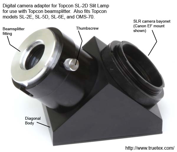
Photo 1. Digital camera adapter for Topcon SL-2D slit lamp beamsplitter
|
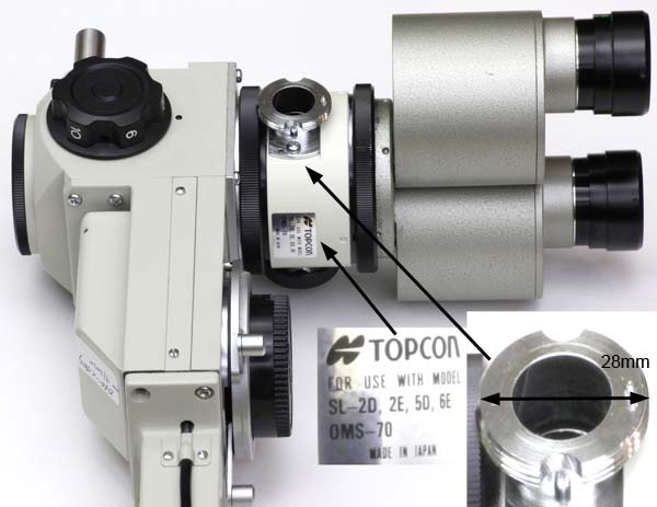
Photo 1a. Identifying the Topcon SL-2D slit lamp beamsplitter.
This is the beamsplitter compatible with this adapter.
Instrument shown is a Topcon SL-5D biomicroscope and binocular.
Compatible Topcon models are SL-2D, SL-2E, SL-5D, SL-6E,
and the OMS-70 operating microscope.
|
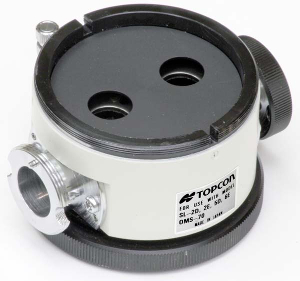
Photo 1b. Overall view of the Topcon SL-2D beamsplitter.
Male thread on top mates to the Topcon binocular.
Female threading ring on bottom mates to Topcon biomicroscope.
Threaded beamsplitter port (28mm diameter) is shown at lower right.
The tiny orientation pin shown projecting to the lower left
at the top of the threaded port may or may not be present.
The digital camera adapter fits the port either way,
with the pin either present or absent.
|
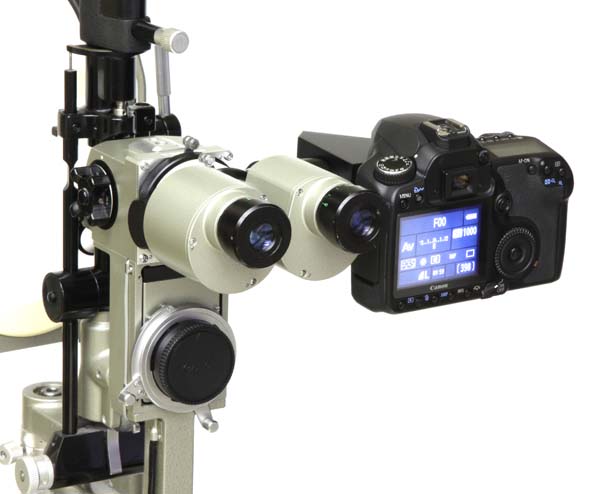
Photo 2. Normal orientation of the adapter and camera.
This puts the camera controls and display conveniently close to the observer's face.
Instrument shown is a Topcon SL-5D, which provides a built-in beamsplitter
with camera coupler centered below the binoculars;
for this model we also provide a different digital camera adapter
for the lower coupler.
For the Topcon SL-2D and SL-2E, this built-in feature is not available,
and to attach a camera requires adding the beamsplitter in front of the binoculars.
|
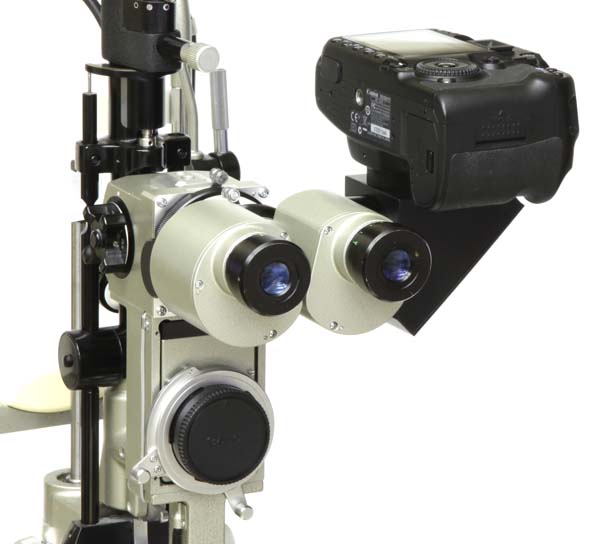
Photo 3. Alternate orientation of the adapter and camera.
This moves the camera away from the observer's face,
which may be more convenient when using
a tethered PC or external HDTV monitor.
To rotate the orientation of the adapter to the instrument,
loosen the adapter thumbscrew.
To rotate the orientation of the camera to the adapter,
loosen the three small setscrews in the camera bayonet fitting.
Other orientations are possible,
such as facing the camera display towards the patient,
which permits a self-examination.
|
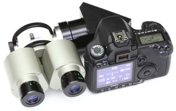
Photo 4. Overall view showing beamsplitter, adapter, camera, and observer binoculars.
Camera shown is a larger Canon type.
Canon Rebel series digital SLRs are smaller and provide more clearance.
|
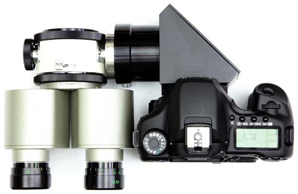
Photo 5. Overall view of beamsplitter, adapter, camera, and binoculars, as seen from above.
|
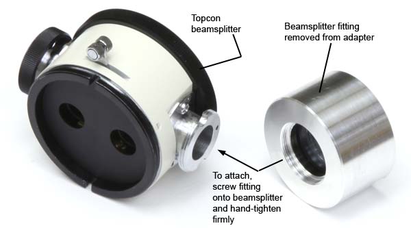
Photo 6. Attaching the adapter's beamsplitter fitting to the Topcon beamsplitter
|
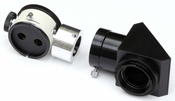
Photo 7. Attaching the adapter's diagonal body to the adapter's beamsplitter fitting.
|
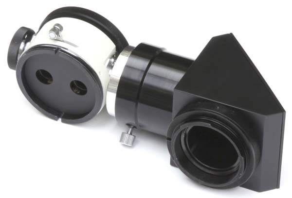
Photo 8. Adapter assembled to beamsplitter, before camera attachment.
Focus the camera by loosening the thumbscrew,
sliding the beamsplitter fitting in or out of the black diagonal sleeve,
and re-tightening the thumbscrew.
This also sets the rotational orientation of the adapter on the beamsplitter.
Rotate the camera orientation on the adapter by loosening three setscrews
in the knurled portion of the bayonet fitting.
|
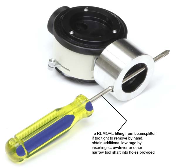
Photo 9. Removing an overly-tightened beamsplitter fitting.
|
Additional notes:
- Replacing the thumbscrew with setscrew:
To lock the orientation of the adapter semi-permanently, remove the thumbscrew from the adapter
and replace with the setscrew provided. Tighten the setscrew with the provided hex key.
You may also use this replacement to solve any mechanical interference of the thumbscrew with the instrument.
- Removing the beamsplitter fitting:
If it should be necessary to remove the adapter from the beamsplitter,
and the the beamsplitter fitting is difficult to remove, use a screwdriver or other tool in the holes provided.
See Photo 9 above.
Copyright 2011 Richard J Kinch.


