INSTALLING THE UPPER-PORT MIRROR SWITCH
for the
TOPCON RETINAL CAMERAS
Models:
TRC-50X and TRC-50IA
Richard J Kinch
http://www.truetex.com
May, 2012
The upper-port mirror switch provides synchronization of the digital camera to the Topcon joystick.
When the Topcon mirror actuates to take a photograph with the upper port,
the mirror movement also mechanically actuates this new snap-action switch.
The switch contact, when
connected to the remote shutter control of the digital camera optically adapted to the upper port,
in turn actuates the digital camera shutter. Thus the shutter lag of the digital camera
and the mirror motion proceed synchronously. When the mirror has settled to
the upper-port position, the digital camera will have had time to open its shutter, and the
digital camera flash synchronization signal will be appropriately timed for the
Topcon instrument to fire the Topcon flash in synchrony with the digital photograph.
Installation of the switch requires that you first remove one of the covers from the upper
unit of the Topcon instrument. Then you attach the switch to the instrument chassis, and
solder one wire to the upper-port interface connector. This task requires some basic
mechanical skills, which are appropriate for a qualified ophthalmological instrument technician.
You may alternatively remove and send us your upper unit for us to perform the upgrade.
You do not need to send us the rest of the instrument.
See separate instructions for removing the upper unit from the instrument base and packing the
upper unit for shipment.
We can also supply a suitable double-wall carton and packing for shipment of the upper unit.
Kit contents: This portion of the digital adapter kit consists of:
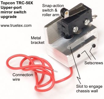
- Switch, bracket, and wire assembly. See Figure 1 below.
- Adapter cable (DB-15 to camera remote and flash sync).
- 1.3mm and 1.5mm size hex keys (Allen wrenches).
- Replacement mirror cushion strip.
- These instructions.

Figure 1. The mirror switch assembly.
Tools required: The following tools are required for installation, and not supplied in the kit:
- Phillips screwdrivers (medium and small).
- Flat-blade screwdriver or coin.
- Small electronics soldering iron with fine tip.
- Fine-gage wire solder with rosin core flux.
- Small blade and solvent to remove and clean off old rubber cushion
- Light oil (if needed, such as sewing machine oil) to lubricate the mirror pivots.
Do not use silicone synthetic oil, as silicone can permanently bond to optical glass surfaces.
Installation and operation of the
adapter lens and other components of the total upgrade package
are described in separate instructions.
These instructions describe only the mirror-switch installation.
In the following, left and right refer to the operator's normal point of view, facing the instrument viewfinder;
front refers to the patient's side of the instrument with the objective lens, rear refers to the operator's
side with the viewfinder. Screws are indicated in their metric dimensions,
such as screw size M3-20 indicating a 3mm thread diameter metric screw with 20mm of thread length.
PRELIMINARY-TESTING THE MIRROR
IMPORTANT NOTE
If the original Topcon upper-port mirror mechanism is sticky, the digital upgrade will work unreliably or not at all.
A sticky mirror is a common situation for instruments which have been in service for many years, due to the normal aging of
mechanical grease and rubber pads.
Perform the following test and, if necessary, correct this problem on your system before proceeding with the
switch installation.
Testing the upper-port mirror actuation:
Before installing the upper-port digital adapter switch, you should check that the upper-port
mirror actuates properly, since having the cover off will provide an easy opportunity to repair any
stickiness due to lack of lubrication or a sticky rubber landing pad.
This test is especially important if you have not been using the upper port in the recent past.
To test the mirror actuation, operate the instrument with the console dial selecting the upper-port 35mm camera instead
of the rear-port 35mm camera, but with nothing attached to the upper port.
When you push the joystick button, as you look down into the upper port, you should see and hear
the mirror flipping up and down smartly, although there will be no instrument flash.
If each push of the joystick button flips the mirror, the mirror should be operating correctly.
The instrument should not beep or otherwise indicate an error.
If instead the instrument locks up with a continuous beeping, this is a signal that the instrument
senses that the mirror is not moving reliably (turn the power off and on to reset the beeping).
In some cases the mirror will operate well after being actuated a few times, until it sits again
for a while and the stickiness returns.
This sticky-mirror problem is easily repaired by replacing the cushion pad (a new one is
supplied in your kit), and perhaps applying a drop of oil on the mirror pivots. Details on this repair are in
the steps below.
If your Topcon instrument has possibly had a digital upgrade installed in the past, you may wish to inspect
under the mirror for an existing retrofitted switch. If present, you will either have to determine
if the old upgrade can remain in place of this switch upgrade, or whether you will have to remove the
old upgrade to install the new one.
INSTALLING THE NEW MIRROR SWITCH
Remove left cover:
To install the upper-port mirror switch, we must first access the interior of the upper unit by
removing the left-side cover, as follows.
This does not require removing the upper unit from the base.
The left-side cover is held on by screws which are removed from
recesses in the opposite-side cover of the upper unit. It may help to have a magnetic-tip
screwdriver or magnetic probe to remove these loose screws from the recesses.
- Turn off the instrument and unplug it from its power source.
- Before removing any knobs on the left side of the unit, turn each of them to their proper positions for later testing on a close test target.
The "0/+/-/A" knob should be at "+", the filter selector and pupil size both at "N", the angle at "50",
and the focus on the test target.
Do not disturb these positions when removing the knobs, since this may intefere with testing later,
before the knobs are reinstalled. Maintaining these normal positions will also help you reinstall the knobs
in their proper orientations later.
- Remove all knobs on the left side of the upper unit by loosening their setscrews with
the 1.5mm hex key. All knobs have one setscrew, except the 20-35-50 angle selector
lever which has two setscrews offset 90 degrees.
- Remove the cover screws as follows, but use care with a proper size Phillips screwdriver if the screws are tight.
A stripped screw head inside a recess will require a difficult repair.
- Remove 1 screw in the recess above the rear port on the upper unit (screw size: M3-20).
Access this screw head from the right side of the upper unit, even though you are removing the left side cover.
- Remove 3 screws in the recesses on the front right edge of the upper unit (screw size: M3-35).
Also accessed from the right side.
- Open the lamphouse cover by loosening the captured, large-headed, slotted screw.
- The upper edge of the lamphouse cover is hinged and retained by tabs inserted into the left-side cover.
Remove the lamphouse cover by disconnecting the tabs.
- Inside the lamphouse cover, remove 1 screw below the examination lamp (screw size: M3-8).
- Remove the left-side xenon flashtube retention post (chrome screw with slotted head), on the
bottom of the flashtube area on the left side.
You may use the 1.5mm hex key, which will fit as a lever into the slot to serve as a convenient tool;
or, turn the post with a stubby flat-bladed screwdriver,
Leave the right-side post and the flashtube itself in place.
- Pull off the left-side cover, which should work free, from the upper-unit chassis.
There are no clips or other retaining features
holding the left-side cover to the instrument or to the right-side cover.
The loose cover will still be connected by some wires inside until the next step.
- Pull apart the LED connector(s) to free the left-side cover completely
from the upper unit, and set the cover aside.
There may be three connectors labeled P314, P315, and P408.
Later versions of the TRC-50X only have a single unlabeled 2-pin connector.
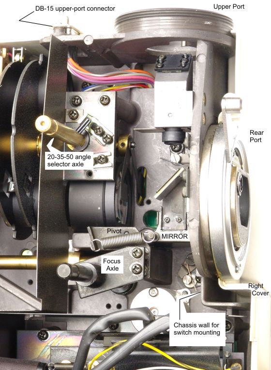
- Identify the mirror and DB-15 connector now exposed by the cover removal.

Figure 2. Locations inside the instrument, prior to switch installation.
This view shows the top rear of the chassis.
Install the new switch mechanically:
- Observe that the snap-action switch is mounted on a metal bracket.
The bracket provides a slot with two small setscrews for fastening the switch-bracket assembly to the instrument.
See Figure 1 above.
- Using your fingertip, gently operate the roller arm on the snap-action switch and observe that it operates with a faint but distinct clicking
sound. You will have to recognize this click later to confirm a proper installation.
- Pivot the mirror to its upper position. The mirror should stay in either position, upper or lower, by itself.
Touch the mirror on its bottom side or edge only; do not touch the mirror surface itself.
-
If you detected a sticky mirror problem with your testing at the start of the installation, or if you just
want to refurbish the mirror mechanism at this opportunity, follow this procedure:
Observe that the mirror when lowered lands upon a small bit of rubber cushion just inside the rear port opening.
This rubber can become sticky with age, and interfere with the mirror actuation.
To replace it, first scrape off the old rubber, then clean the residue with alcohol and a swab.
Apply the new cushion strip supplied in the kit by removing the plaid strip to expose the fresh adhesive side.
Place a tiny bit of light oil
on the tip of a toothpick or other probe, and touch this to the ends of the axle on which the mirror pivots.
Use just enough oil to wet the axle slightly; do not allow any oil to contaminate other parts of the instrument interior.
Operate the mirror by hand to verify that it moves freely and without sticking to the new cushion.
- Slide the switch bracket over the chassis wall below the rear camera port, all the way until the edge
of the chassis wall touches the inside end of the slot.
This will be a trial adjustment, so tighten the setscrews (1.3mm hex key) slightly against the chassis,
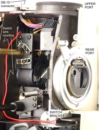
just enough to hold the bracket in position. See Figure 2 above, and Figure 3 below.
- Lower the mirror gently so that it seats against the cushion and the new switch roller.
Confirm that the snap-action of the switch clicks audibly as the mirror raises and lands.
This sound may be very faint, but still distinct.
Loosen the setscrews and adjust the bracket position if needed to align the switch for correct snap-action
with the mirror. Once correctly adjust the snap-action of the switch,
tighten the setscrews snugly.
- Clean the mirror optical surface if needed. This is a coated, first-surface mirror, so use proper
technique when cleaning.

Figure 3. Locations inside the instrument, after switch installation.
This view shows the top rear of the chassis.
Connect switch to upper-port connector:
- Observe that the DB-15 upper-port connector is attached to the chassis with two screws.
- Remove the DB-15 screws.
- Lift the connector up as far as the slack on the wires will permit, but do not stress the soldered connections.
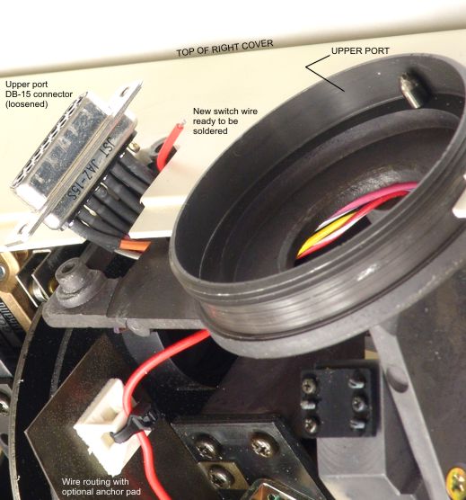
See Figure 4 below.
- Route the new loose wire from the new switch as shown in the figure: along the bottom of the compartment, below the focusing
mechanism axle shaft, up between the sheet metal and the angle-change axle shaft, and up to the inside location of the connector.
- Observe the pin numbering on the DB-15 connector. Pin numbers are embossed in tiny digits on the connector body.
Indicate the numbering by marking a dot next to pin 1 on the solder side.
- Observe that there is no existing connection to pin 8 of the DB-15 connector.
If there is a connection, then you have some existing modification of the instrument, which is beyond the scope of this document.
- Apply solder to the solder cup of pin 8 of the DB-15 connector.
Pin 8 is the end of the first row of pins, opposite the pin 1 end.
Use a fine-tip soldering iron with fine-gage rosin-core wire solder.
Take care not to mar the plastic of the left-side cover with the hot soldering iron.
Take care not to short the solder cup to adjacent pins with too much solder.
- Solder the new switch wire to pin 8 of the DB-15 connector.
- Inspect the connector to confirm that you have a good solder joint for the new wire on pin 8,
and that the other wires remain connected.
- Reassemble the DB-15 connector to the upper unit with the two screws.

Figure 4. DB-15 soldering arrangment.
Note routing of wire and use of optional anchor pad.
Testing the installation before reassembly:
Before replacing the upper unit cover, you should test that the installation was successful.
Caution: Hazardous voltages are exposed when the cover is off the upper unit and the instrument
is energized, especially around the xenon flashtube on the bottom.
Do not touch any electrical contacts inside the exposed instrument while it is powered on.
- Install the digital camera adapter lens, digital camera body, and interface cable, using
the separate instructions provided.
- Perform the following tests in a darkened room. This is necessary because bright ambient light
may interfere with the optical position sensors on the exciter filter wheel.
- On the Topcon console, select 35mm, upper, and 18 watt-second flash.
- Take a few test exposures to confirm that the Topcon
joystick actuates the digital camera shutter, and the the Topcon flash fires in response to
the digital camera.
- Remove the camera and adapter, so that you may reassemble the cover as follows.
Reassemble the cover: Reassembly of the left-side cover is the reverse of the disassembly above.
This completes the installation.
Copyright 2009, 2010, 2011, 2012 Richard J Kinch.


