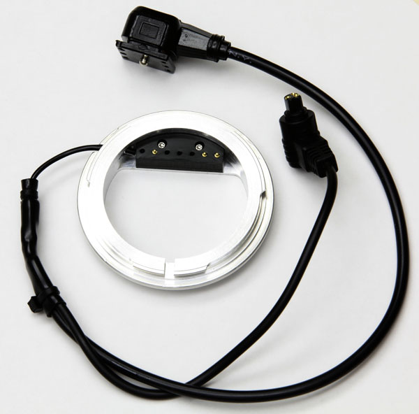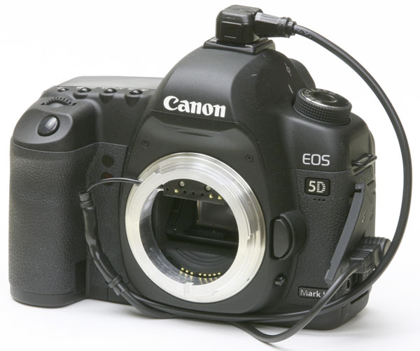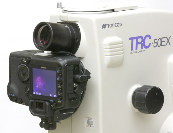
Figure 1. Digital camera adapter assembly for the rear port of the Topcon TRC-50EX.
Cabling terminates in a hot shoe connector (top) and Canon N3 remote shutter connector (right).
Richard J Kinch
http://www.truetex.com
Revised: April, 2016
This document describes how to install and operate the digital camera upgrade kit for the rear port of the Topcon TRC-50EX, TRC-50IX, and TRC-50DX series retinal cameras.

Other components you must obtain separately:
Optional components you may wish to obtain separately:
Familiarize yourself with the digital camera: If the digital SLR camera is new to you, be sure the learn about the following features which will be used for retinal photography: On/off switch, mode switch "M" setting for manual operation, attaching and removing lenses, remote shutter release connector, viewing photos on the camera, transferring photos to a computer. The following settings are critical to proper operation, so be familiar with how to set them: manual exposure time, drive mode, self-timer, white balance, and ISO speed.

Attach the adapter to the Canon camera: Identify the Canon bayonet side of the adapter, which the all-aluminum side. This is mechanically a standard Canon EF mount bayonet, such as is used on Canon EF lenses for the EOS camera series, except it has no electrical contacts for the Canon side. The Canon bayonet shape on the adapter matches that of any Canon lens you might have. Via the adapter, the Topcon instrument will appear to the Canon camera to be an elaborate, manual-focus EF lens. Attach the Canon camera to the EF lens mount in the usual way, that is, by inserting the bayonet while aligning the red dots and turning the adapter. Take care not to pull on the attached cable.
It is normal for the bayonet engagement to be somewhat stiff, which makes locking the adapter difficult since there is no lens body to hold onto. To ease the locking twist on the adapter into the Canon bayonet receptacle, insert a small screwdriver or other shaft across the slot on the Topcon side of the adapter, and use it as a handle to gently turn the adapter clockwise, as if attaching a normal Canon lens.
Connect the interface cable to the Canon digital camera: The interface cable has a split end for the Canon digital camera. The split end terminates in a remote shutter control connector (Canon N3 connector) and a hot shoe connector. Insert these two connectors into the remote shutter release socket (on the side of the Canon camera body) and the hot shoe receptacle (on top of the Canon camera body). Observe Figure 2 above carefully for the proper orientations of the connectors and cabling. The remote connector cable will be exiting to the front of the camera. The hot shoe connector slides into the rear of the hot shoe receptacle, with the cable exiting to the left side of the camera. Dress the cable loosely around the bottom of the camera body. Dress the optional cables and manage them on the instrument: Install the optional USB interface cable for tethering to a PC, and the optional AC power supply cable and adapter to eliminate the need for a charged battery. Once these cables to the digital camera are installed, you may wish to dress them with cable ties so that they run along the right side of the instrument and the original grey Topcon cable to the base, and underneath the instrument base to the left side of the instrument. From there you may connect to the AC power source, and the USB computer receptacle. Make sure that the upper unit of the Topcon instrument is able to travel and swing across its full range of motion without binding or chafing the cables.
Remove any old film camera and the bayonet arm from the Topcon instrument: Lift the Topcon bayonet arm to remove the old MT-10 film camera or other accessory from the rear port. Use a Phillips screwdriver to remove the screws holding on the arm from the Topcon bayonet receptacle ring. You must remove the arm and its handle, because they will interfere with the close fit of the digital camera. Reinsert the screws to the rear port receptacle. Retain the arm should you wish to later revert the digital upgrade.

Attach the camera adapter to the Topcon instrument: (If using a Canon 6D model DSLR, study the handgrip modification paragraph below before proceeding with this paragraph.) The digital camera with adapter attaches upside-down to the rear port of the Topcon instrument. This inverted orientation avoids mechanical interference with the instrument, and also yields photos that are upright, since Topcon used an inverted method on their instrumentation film camera bodies. This attachment works in the usual way described in the Topcon documentation for attaching a camera to the rear port: Make sure the handle side of the Topcon receptacle is "up" (clockwise) all the way to the stop. Insert the adapted digital camera into the bayonet receptacle, routing the cable between the Topcon viewfinder eyepiece and the bottom (facing upwards) of the camera body. Press the adapted camera firmly so the bayonet and receptacle fully mate, and push the Topcon bayonet receptacle ring down (counterclockwise) with a tool so that it rotates and locks the attachment. Since you previously removed the arm normally used to actuate the Topcon bayonet ring, use a long thin tool (screwdriver, long wooden swab stick, or other probe) to reach in between the camera body and the instrument to the left of the Topcon viewfinder eyepiece, pushing down on the handle-mounting notch of the bayonet receptacle ring to rotate it to the locked position. This locking mechanism will engage smoothly, but you must press the camera firmly against the receptacle as you rotate the ring down, while also wrangling the loose cables from being pinched or stretched. Take care when applying force with the tool to not inadvertently catch or pull the thin wiring that exits the adapter near the receptacle notch, since this could damage the wiring. Be aware that the ring will not begin to rotate unless the adapter is fully engaged into the receptacle, and it requires some care and skill to coordinate these hand and tool operations. Do not apply more than a moderate force to the task; if the mechanism fails to engage and turn, then correct the loose engagement instead of attempting more force.
If the bayonet mechanism fails to engage as you expect, remove the adapter from the Canon camera, and make a trial of engaging and locking the loose bayonet adapter alone into the Topcon bayonet receptacle. This trial will verify and practice your performance of the tricky mechanics. Once you have succeeded at attaching the loose adapter, remove and reinsert it on the Canon camera, and try the full assembly into the Topcon bayonet receptacle. If this is still not successful, a handgrip modification may be required as follows.
Canon 6D handgrip modification for easier fit: The fit of the Canon DSLR body to the instrument when attached with the bayonet adapter will be very close to the Topcon case. The top of the rubber handgrip on the Canon DSLR body (near the Canon shutter button) will approach and may slightly interfere against the beige Topcon case when the adapted DLSR body is pressed forward to completely engage the Topcon bayonet receptacle. With the Canon 5D Mark II and Mark III models, this interference is slight, and coordinating a firm pressure forward on the rear of the DSLR body while simultaneously rotating the Topcon bayonet receptacle ring should suffice to engage and complete the locking mechanics without modification. The Canon 6D model, however, provides a very slightly larger handgrip which may present enough interference to prevent seating the adapter bayonet fully into the Topcon bayonet receptacle. In this case you should modify the Canon 6D handgrip by neatly shaving approximately 2mm thickness from the very top of the rubber handgrip, using a sharp razor knife, and a similar amount of material from the hard plastic adjacent to the rubber, using a flat file to flatten the adjoining area of plastic. This removal will not affect the performance of the DSLR, although it will be a permanent modification to the handgrip.To perform this modification neatly and precisely, start with first marking the area to be removed with a trial fit as follows: Make a trial engagement of the DSLR camera bayonet adapter into the Topcon bayonet receptacle, and while holding the engagement fully forward, mark the area of interference on the DSLR hard plastic with a pencil from underneath. Then remove the DSLR and perform the shave of the rubber and the filing of the hard plastic at the area you have marked. Remove only the top edge of the handgrip, as you observed was interfering in the trial fit.
Adjust instrument for a fixed test subject: Turn on the retinal camera and set the instrument controls to select the rear port as if using a 35mm camera attachment there. Tape a business card or other flat, high-contrast, detailed subject to the patient headrest to serve as a fixed test target. Frame and focus a view of this target using the Topcon viewfinder in the normal fashion, perhaps pulling away from the subject and using the "+" refraction compensation, as for anterior segment views. Set the retinal camera flash intensity to the lowest possible setting (one or one-half step above "NF" (no-flash)).
Adjust Canon camera settings: Configure the Canon camera as follows:
Take test subject exposures: Focus and align on the test subject using the instrument viewfinder in the usual way. Press the joystick button to trigger an exposure. At the moment of exposure, listen for the Canon camera mirror flip and shutter mechanisms operating, along with the Topcon mirror flipping. Observe the light of the retinal camera flash on the subject. Immediately after the exposure, the Canon camera should momentarily display a view of the image on the rear display. Use the Canon menu buttons to review exposures. Zoom in when reviewing images to verify that image is sharply in focus when the viewfinder was also in focus. Note that the full resolution of the digital camera is much finer than the instrument resolution, so the highest-resolution images will not appear in focus when zoomed in completely.
Take live subject exposures: It is most convenient to obtain a cooperative, well-dilated colleague or patient for your first live retinal digital image tests. Collimate and focus on the retina in the usual way with the viewfinder, using the joystick button to take exposures. Check the images for exposure brightness and adjust the flash intensity to compensate; the digital camera may be more sensitive than the usual film and lower flash intensity is usually indicated.
Extended framing: The digital camera does not apply a field mask to the retinal image, and thus shows a slightly wider angle of view than the film camera, which the film camera masked off. This extra area of view is normal in the digital upgrade. Should you wish to have a masked look to your photos, such as for publication, you may apply it via a photo post-processing application on a computer
The instrument is effectively a manual lens: As noted above, the Topcon instrument in effect becomes a manual lens for the digital camera. The digital camera will thus have no focus or aperture settings, as these are controlled by the Topcon instrument. The exposure adjustment will depend only on the Topcon flash energy and the ISO speed setting of the digital camera. Changing the exposure time will not affect the exposure intensity, as this is a function of the flash energy and not the time the shutter was opened. Using a shorter exposure time setting than recommended above will possibly miss the Topcon flash altogether and result in a dark photo. Using a longer exposure time will have no effect other than to possibly delay the next photo.
Ignore the film-winding error: The digital camera adapter does not return a signal to the Topcon instrument verifying that the film winding succeeded. On some versions of the Topcon instrument, the Topcon console will flash an "F-Err" code after each exposure as if the camera were out of film. Not all Topcon system exhibit this behavior, but if so, this is normal and may be ignored. The code message imposes a minimum interval between exposures of 3 seconds. See the next section for a workaround if you require more frequent exposures.
Workaround for film-winding error: If the 3-second delay between exposures is too long, you may wish to apply the following workaround, where you switch the upper and rear-port solenoid connectors inside the Topcon upper unit. Thereafter, when you set the Topcon console to the upper-port mode, the instrument actually operates the rear-port light path. Since the upper-port mode does not expect film-winding messages, this avoids the error and the delay between exposures. This workaround is not available if in addition to the rear-port camera you are also using an upper-port adapter for a second digital camera, such as an upper-port infrared camera for ICG on the TRC-50IX.
To apply the workaround:
To operate the digital camera on the adapted rear port, you must now set the Topcon console to the UPPER setting. This setting allows you to shoot at the maximum rate of the instrument, which is somewhat more frequently than once per second. You may wish to cover the original UPPER label with a new label to indicate it now selects the rear-port digital camera. Cover the LOWER label as well, since this is now disconnected.
This modification does not permit use of the upper port, only the rear port. It also does not illuminate the LED data indicators and timer in the rear-port image, so these numbers will no longer appear in the digital camera images (timing information is however available in the JPEG photos EXIF data). Should you wish to revert the Topcon instrument to its original UPPER/LOWER functioning, you can simply reverse the above steps.
Adjusting the ISO speed of the digital camera: The Canon digital cameras offer a range of ISO speeds, from 64 or 100 up to 1600 or higher. This provides you another variable determining the exposure of the digital photograph, along with the flash energy on the Topcon instrument. Higher speeds up to about ISO 1600 will enhance the sensitivity of the camera while not introducing much noise. You can use these higher settings to obtain a proper exposure in color photography while using minimal flash energy of 12 or 18 watt-seconds. Speeds of ISO 3200 or more will begin to introduce a noticeable degree of speckled noise into the pixels of the photograph, especially considering that the retinal image is by nature of very low contrast. Speeds of ISO 1600 to ISO 3200 may be useful for fluorescein angiography, which will then properly expose with perhaps 50 watt-seconds of flash energy, much less than what was needed for 35mm film exposures, and much less dazzling and fatiguing to the subject eye.
Use the histogram feature of the digital camera to analyze your retinal images for proper exposure level and to observe the degree of contrast. The position of the hump in the histogram indicates the exposure level, which should not be at the extreme dark or light ends of the range, while the width of the hump indicates the contrast of the retinal image elements. The retina is a low contrast scene by nature, so even in the best photographs, you can expect the histogram width to cover only about 1/4 to 1/3 of the range.
Using an AC adapter on the Canon camera: To avoid having to worry about having a charged Canon camera battery, you may wish to purchase the Canon optional item that powers your model camera from an AC adapter.
Lowering resolution on the camera: Since the highest resolution images of the camera are finer than the theoretical optical resolution of the instrument, you may wish to set the camera to record lower-resolution images. This will decrease storage space and improve tethered transfer times.
Tethering software: If you want to have live previewing and capture of photos on a computer while shooting with the Canon camera, consider using "tethering" software. This type of application uses a "tether" from the camera to the computer via a USB cable. A simple version is included with the Canon camera software support disc. DSLR Remote Pro (http://www.breezesys.com/DSLRRemotePro/) is one popular aftermarket package sold for this application.
Alternate Canon camera models: Only full-frame Canon digital SLR cameras (such as the model 5D, 5D Mark II, 5D Mark III and future models based on the EF lens mount and N3 remote shutter control) work properly with this rear-port adapter. Smaller format cameras such as the Canon Rebel series, the Canon 40D, or the Canon 50D crop the frame by an 0.6X factor, so much of the retinal image will be cropped out, and the built-in flash enclosure will mechanically interfere with the close fit of the adapted camera to the Topcon instrument. These smaller-format cameras are however compatible with our upper-port adapter for this Topcon instrument.