Making Digital Camera Microscope Adapters
Richard J Kinch, PhD
Updates: November, 2024.
 This page describes the custom adapters and optical engineering assemblies I make to fit a variety of cameras, microscopes, and medical instruments.
I engineer and fabricate these adapters personally using my own CAD facility, optical engineering laboratory, machine shop, and
electronics workbench.
For most of these simpler mechanical adapters, I charge $175 to $375 (USD), depending on the complexity.
Adapters incorporating optical elements are more complex and typically cost $500 to $950, including the optics.
Complete kits for medical and scientific instruments, with custom mechanical, optical, and electronic components, range from $800 to $6000.
Old and new optical instruments are thereby fitted into the modern age of digital imaging.
I also research and develop new instrumentation designs for larger projects which involve much higher costs.
This page describes the custom adapters and optical engineering assemblies I make to fit a variety of cameras, microscopes, and medical instruments.
I engineer and fabricate these adapters personally using my own CAD facility, optical engineering laboratory, machine shop, and
electronics workbench.
For most of these simpler mechanical adapters, I charge $175 to $375 (USD), depending on the complexity.
Adapters incorporating optical elements are more complex and typically cost $500 to $950, including the optics.
Complete kits for medical and scientific instruments, with custom mechanical, optical, and electronic components, range from $800 to $6000.
Old and new optical instruments are thereby fitted into the modern age of digital imaging.
I also research and develop new instrumentation designs for larger projects which involve much higher costs.
Besides the mechanical attachment, these adapters apply one of several optical principles to couple the camera to the microscope,
including:
- Afocal (through the normal eyepiece to inexpensive small-format digital cameras)
- Focal (from a photoport to digital SLR (DSLR) camera bodies)
- Focal (from a photoport to small-format digital cameras via a relay lens)
- Afocal (through a custom photo-eyepiece for large-lensed digital cameras)
 As an example, you can inspect a 3D solid model for a typical adapter [Autodesk DWF file, 26 KB].
(This requires the free Autodesk DWF Viewer).
The viewer allows you to rotate ("orbit"), pan and zoom the 3D model so you can see exactly what we are discussing.
You can also view the mechanical drawing [PDF file, 30KB].
As an example, you can inspect a 3D solid model for a typical adapter [Autodesk DWF file, 26 KB].
(This requires the free Autodesk DWF Viewer).
The viewer allows you to rotate ("orbit"), pan and zoom the 3D model so you can see exactly what we are discussing.
You can also view the mechanical drawing [PDF file, 30KB].
|
 Here is another 3D model that shows a typical adapter and eyepiece nesting [Autodesk DWF file, 28 KB].
Rotate the model (using the "orbit" tool in the viewer) so you can see how the custom adapter closely fits the supplied microscope eyepiece.
Here is another 3D model that shows a typical adapter and eyepiece nesting [Autodesk DWF file, 28 KB].
Rotate the model (using the "orbit" tool in the viewer) so you can see how the custom adapter closely fits the supplied microscope eyepiece.
|
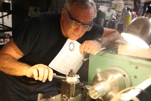
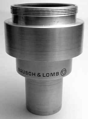
The metalworking process may be illustrated by the first such adapter I made was some years back.
This was for a Sony DSC-S30 digital camera, mounting to a Bausch and Lomb microscope.
This creates a system for high-quality, wide-field photomicrography.
The lens of the Sony DSC-S30 camera provides a 37 mm inside diameter x 0.75 mm inside threads, and the
microscope eyepiece provides a smooth 1.138 inch outer diameter cylinder.
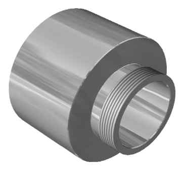
Thus the adapter will consist of a turret with outside threads to mate to the camera lens,
and an inside bore to slip snugly over the microscope eyepiece.
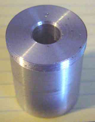
 The first dimensional step is to turn down the cylinder, leaving a raised
ridge of 37 mm diameter, ready to take on the outside threads. I chose to thread
a length of 5 mm, which was about twice the length of the inside threads on the
camera turret. Using the threading bit to turn the smooth diameter makes it
easy to leave 60 degree bevels on all the stepped edges.
I was happy to find that the 0.75 mm metric thread pitch is available on the minilathe
using the standard set of change gears (see the Yahoo
7x10minilathe group files
area for tables of using change gears for metric threading).
The photos show the work progressing on an aluminum billet I made as a casting experiment, and the
casting flaws show up as dark spots or flecks.
For later versions, I have been using aerospace grade aluminum stock.
The first dimensional step is to turn down the cylinder, leaving a raised
ridge of 37 mm diameter, ready to take on the outside threads. I chose to thread
a length of 5 mm, which was about twice the length of the inside threads on the
camera turret. Using the threading bit to turn the smooth diameter makes it
easy to leave 60 degree bevels on all the stepped edges.
I was happy to find that the 0.75 mm metric thread pitch is available on the minilathe
using the standard set of change gears (see the Yahoo
7x10minilathe group files
area for tables of using change gears for metric threading).
The photos show the work progressing on an aluminum billet I made as a casting experiment, and the
casting flaws show up as dark spots or flecks.
For later versions, I have been using aerospace grade aluminum stock.
|
 Next I mounted the tailpiece onto the lathe with a drill chuck and
1/2-inch drill bit, and bored a hole into the center of the piece.
Next I mounted the tailpiece onto the lathe with a drill chuck and
1/2-inch drill bit, and bored a hole into the center of the piece.
|
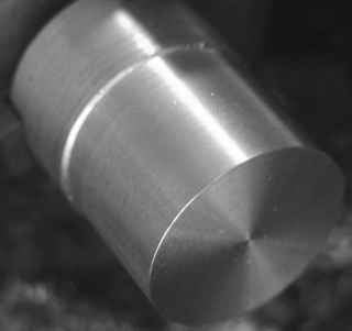
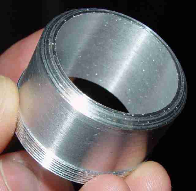 With that 0.500 inch starter hole drilled, I was ready to start boring out the
1.138 inch inside diameter that would receive the microscope eyepiece.
For this I used carbide boring bar bits that reached the 1" depth of the finished part.
(Making the boring bar tool holder is the subject of another of my project descriptions.)
After boring the hole a few thousandths oversize, I had a close fit of the
adapter to the eyepiece. I finished the part by cutting it from the cylinder
using a parting tool. I cut a length that maximized the fitted depth,
but still let the camera lens come to rest on the eyepiece.
The photo shows the finished adapter.
With that 0.500 inch starter hole drilled, I was ready to start boring out the
1.138 inch inside diameter that would receive the microscope eyepiece.
For this I used carbide boring bar bits that reached the 1" depth of the finished part.
(Making the boring bar tool holder is the subject of another of my project descriptions.)
After boring the hole a few thousandths oversize, I had a close fit of the
adapter to the eyepiece. I finished the part by cutting it from the cylinder
using a parting tool. I cut a length that maximized the fitted depth,
but still let the camera lens come to rest on the eyepiece.
The photo shows the finished adapter.
|
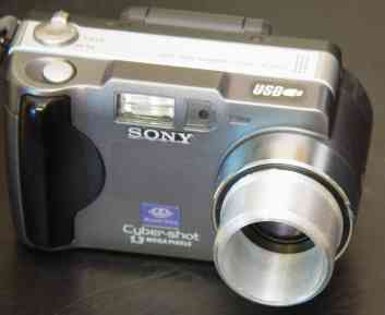
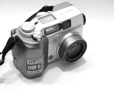
Below is a view of the Sony DSC-S30 camera, with and without the adapter mounted.
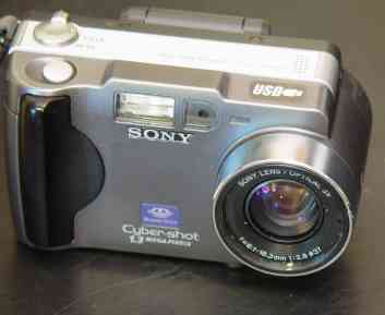
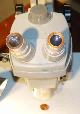 This is an old Bausch and Lomb inspection microscope. This US-manufactured item
isn't made any more, but when new they sold for about $2000. The optics are
superb, providing a wide, flat field at a variety of zoom magnifications from
7x to 30x. Today, you can find them used on eBay for perhaps $500 or less, or
you can buy a similar imported item for about that price new.
This is an old Bausch and Lomb inspection microscope. This US-manufactured item
isn't made any more, but when new they sold for about $2000. The optics are
superb, providing a wide, flat field at a variety of zoom magnifications from
7x to 30x. Today, you can find them used on eBay for perhaps $500 or less, or
you can buy a similar imported item for about that price new.
The turrets of the binocular
eyepieces have the virtue of being smooth, even aluminum cylinders. This allows
a simple cylindrical adapter to nest on top of the eyepiece.
|
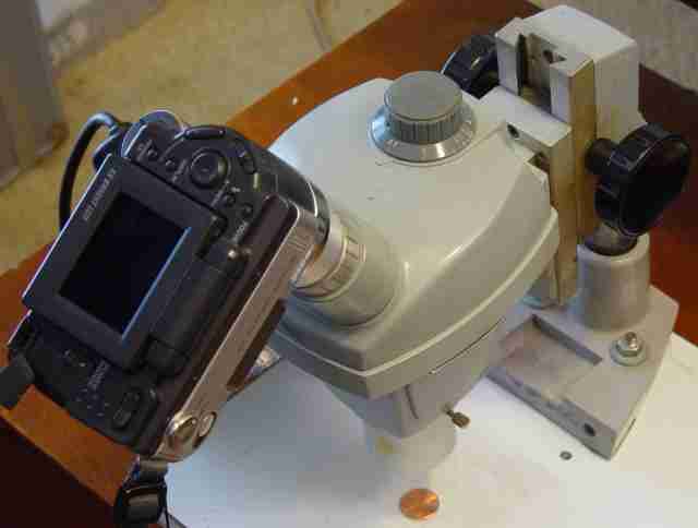 This is the camera mounted on the microscope eyepiece.
The adapter aligns and rigidly fixes the camera to the microscope.
The camera lens protrudes in such a way as to touch the eyepiece, so I should apply
a bit of vinyl tape as a cushion, or perhaps machine a spacer ring to insert as a standoff.
I may add winged setscrews in the future to lock the camera on the eyepiece.
This is the camera mounted on the microscope eyepiece.
The adapter aligns and rigidly fixes the camera to the microscope.
The camera lens protrudes in such a way as to touch the eyepiece, so I should apply
a bit of vinyl tape as a cushion, or perhaps machine a spacer ring to insert as a standoff.
I may add winged setscrews in the future to lock the camera on the eyepiece.
|
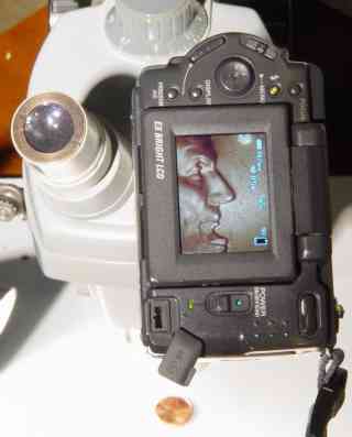 This shows the camera turned on, with the camera display imaging the
the microscope's magnified view of a coin.
The optical system of this camera is well-matched to the exit pupil of this microscope.
By adjusting the camera zoom one can either get a vignetted photo of the full
field of the microscope, or a full-framed photo of the center region of the microscope
view. Both modes are desirable for various purposes. The photo below shows the
full-frame mode.
This shows the camera turned on, with the camera display imaging the
the microscope's magnified view of a coin.
The optical system of this camera is well-matched to the exit pupil of this microscope.
By adjusting the camera zoom one can either get a vignetted photo of the full
field of the microscope, or a full-framed photo of the center region of the microscope
view. Both modes are desirable for various purposes. The photo below shows the
full-frame mode.
|
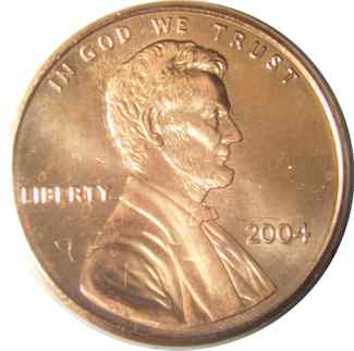
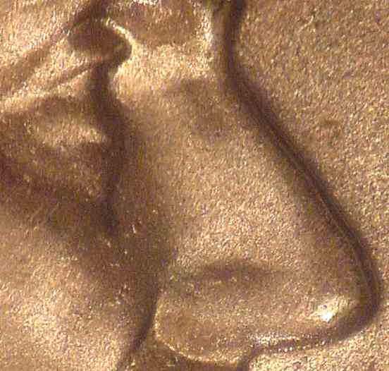 This is a portion, at full resolution, of a photo taken by the Sony camera in the above setup.
The object shown is a Lincoln penny, of which you are seeing part of Lincoln's face.
I measured the features shown with calipers, giving a true height of the representation as 0.070 in.
The digital image is 526 pixels high.
Thus the system resolves about 7500 pixels/inch, which is 7.5 pixels/thousandth-inch, 130
microinches/pixel, or 3.4 microns/pixel.
If we assume your display renders 96 pixels/inch, then the effective magnification is
about 78x (= 526 pixels / 96 pixels/in / 0.070 in).
The camera resolves 1472 x 1104 pixels (not much by today's standards),
so the camera and microscope can photograph a physical area of about 0.2 by 0.15 true inches at this level of detail;
the full field to the eye view in the microscope is about a 0.25 inch diameter circle.
The microscope field zooms from about 1 inch at 7x magnification, to 1/4 inch at 30x.
This is an amazing quality of result given that this camera sells for under $200, and the
microscope sells used for about $500. Such a system would have cost many $1000s, and required
costly film processing, not many years ago.
This is a portion, at full resolution, of a photo taken by the Sony camera in the above setup.
The object shown is a Lincoln penny, of which you are seeing part of Lincoln's face.
I measured the features shown with calipers, giving a true height of the representation as 0.070 in.
The digital image is 526 pixels high.
Thus the system resolves about 7500 pixels/inch, which is 7.5 pixels/thousandth-inch, 130
microinches/pixel, or 3.4 microns/pixel.
If we assume your display renders 96 pixels/inch, then the effective magnification is
about 78x (= 526 pixels / 96 pixels/in / 0.070 in).
The camera resolves 1472 x 1104 pixels (not much by today's standards),
so the camera and microscope can photograph a physical area of about 0.2 by 0.15 true inches at this level of detail;
the full field to the eye view in the microscope is about a 0.25 inch diameter circle.
The microscope field zooms from about 1 inch at 7x magnification, to 1/4 inch at 30x.
This is an amazing quality of result given that this camera sells for under $200, and the
microscope sells used for about $500. Such a system would have cost many $1000s, and required
costly film processing, not many years ago.
I don't know the resolution limits of the microscope optics, but they're probably better
than what the Sony DSC-S30 camera is resolving in this setup.
If that is true, then a higher-resolution camera would resolve more detail.
I have a much better digital camera now, but it uses a large-aperture lens that isn't as
well-matched to the microscope aperture, resulting in a severe vignette in the image.
As a general optical design principle, one would want a small camera lens for this kind of
behind-the-eyepiece microscopy.
With camera lenses, bigger is usually better, since you can gather more light.
But digital cameras can (and typically do) have
very small, but nevertheless high-quality, lens systems, because the CCD electronic imaging
devices are so much smaller than film formats.
The light available is determined by the microscope optics, not the camera.
Many digital cameras today (2004) seem to be using imaging chips and lenses that are very close to
the human eye in physical scale. This is a wonderful thing for those wanting to adapt the cameras to
microscopes, because no optical adapters (such as a negative "relay lens") are needed, just mechanical arrangements.
The pupil of the human eye may be assume to be about 4 to 5 mm in diameter when viewing microscope images.
A good microscope will provide an exit pupil of similar diameter, and the camera lens should match this as well.
Not so wonderful for the would-be photomicrographer is the trend away from putting filter mount
threads on the lens turrets, even on the more expensive consumer models; later versions of my Sony
DSC-S30 have a telescoping lens contraption that regrettably features no thread mount.
If you're looking to buy a digital camera with hopes of photomicrography, look for one with a fixed, threaded
turret, with the inside thread diameter significantly larger than the microscope eyepiece you hope to use.
Even if your camera has an extending/retracting lens turret, you may find an optional adapter tube
(see Nikon, Canon, and Olympus examples below)
that provides both room for the turret and filter threads for a further adapter.
As a last resort, one can fit a sleeve machined just larger than the turret, with one or more screws for clamping
to the turret itself.
|
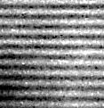 The original microscopy experiments above were done in 2002. In 2004, I repeated them with the same microscope,
but using a higher-resolution camera (Sony DSC-F707, 2560 x 1920 resolution = 5 megapixels) and an Edmund Scientific
Co. resolution test target (gratings from 5 lines/mm to 200 lines/mm). This apparatus proved a resolution of 160 lines/mm
(4000 lines/inch), or equivalently to 8000 pixels/inch (3 microns/pixel).
The photograph shows a contrast enhancement of the 160 lines/mm grating.
This is about the same resolution achieved directly viewing into the microscope eyepiece with the naked eye,
and is the essential resolution limit imposed by the inspection microscope.
Thus a higher-resolution camera does not
necessarily translate into higher resolution photomicroscopy images,
because the microscope itself introduces the resolution-limiting optical elements.
This is a proper approach to the task, where the camera should be chosen to capture an image of some specified
area, consistent with the resolution limits and field size of the microscope.
The original microscopy experiments above were done in 2002. In 2004, I repeated them with the same microscope,
but using a higher-resolution camera (Sony DSC-F707, 2560 x 1920 resolution = 5 megapixels) and an Edmund Scientific
Co. resolution test target (gratings from 5 lines/mm to 200 lines/mm). This apparatus proved a resolution of 160 lines/mm
(4000 lines/inch), or equivalently to 8000 pixels/inch (3 microns/pixel).
The photograph shows a contrast enhancement of the 160 lines/mm grating.
This is about the same resolution achieved directly viewing into the microscope eyepiece with the naked eye,
and is the essential resolution limit imposed by the inspection microscope.
Thus a higher-resolution camera does not
necessarily translate into higher resolution photomicroscopy images,
because the microscope itself introduces the resolution-limiting optical elements.
This is a proper approach to the task, where the camera should be chosen to capture an image of some specified
area, consistent with the resolution limits and field size of the microscope.
|
 The advantage of a better camera is chiefly the larger field size it can capture at the resolution limits.
To the left is a thumbnail of another Lincoln penny image taken
with the higher-resolution camera at something less than the maximum magnification.
See the full 1600x1600 resolution image here [155 KB JPG file], which makes a 20X
image on a typical 96 dpi monitor.
We can see a field of up to 0.9 inches diameter at this resolution (2000 pixels/inch),
with the whole item imaged at once instead of just the nose.
Using combinations of the camera and microscope zoom lenses, the magnification can be increased by another factor
of about four to 80X or so, but vignetting will start to reduce the size of the object area.
The advantage of a better camera is chiefly the larger field size it can capture at the resolution limits.
To the left is a thumbnail of another Lincoln penny image taken
with the higher-resolution camera at something less than the maximum magnification.
See the full 1600x1600 resolution image here [155 KB JPG file], which makes a 20X
image on a typical 96 dpi monitor.
We can see a field of up to 0.9 inches diameter at this resolution (2000 pixels/inch),
with the whole item imaged at once instead of just the nose.
Using combinations of the camera and microscope zoom lenses, the magnification can be increased by another factor
of about four to 80X or so, but vignetting will start to reduce the size of the object area.
|
The Sony DSC-S85 camera with the Sony VAD-S70 adapter (45mm to 52mm lens adapter) provides
a 52mm filter thread.
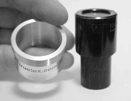
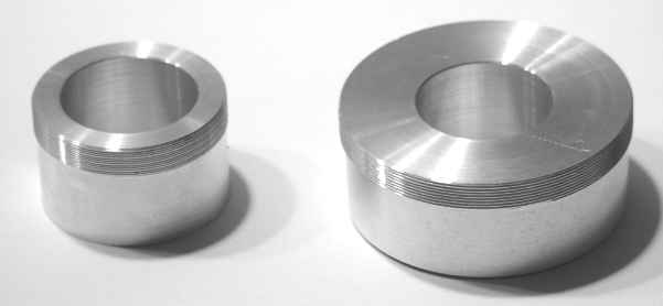 Here are some more digital camera microscope adapters I made for a customer.
These slide over a slightly smaller 1.135" eyepiece on a Bausch and Lomb microscope.
The smaller item on the left provides an M41x0.5 thread for an Olympus C-3020 digital camera.
The larger item on the right provides an M62x0.75 thread for an Olympus E-10 or E-20 digital camera.
I used commercial 6061 aluminum round stock for these.
The threads on the left look uneven because of an interference pattern (moire effect) on the digital photo.
Note the optical illusion which makes the bore look larger on the left adapter compared to the right;
they are in fact equal.
Here are some more digital camera microscope adapters I made for a customer.
These slide over a slightly smaller 1.135" eyepiece on a Bausch and Lomb microscope.
The smaller item on the left provides an M41x0.5 thread for an Olympus C-3020 digital camera.
The larger item on the right provides an M62x0.75 thread for an Olympus E-10 or E-20 digital camera.
I used commercial 6061 aluminum round stock for these.
The threads on the left look uneven because of an interference pattern (moire effect) on the digital photo.
Note the optical illusion which makes the bore look larger on the left adapter compared to the right;
they are in fact equal.
|
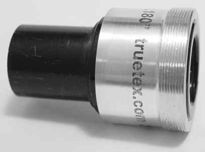
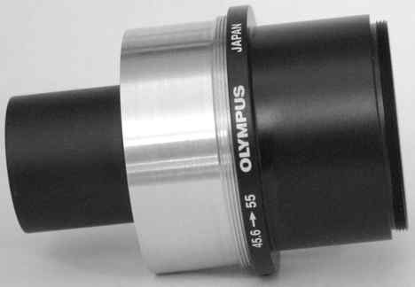
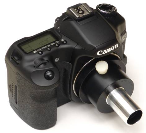
The photos below show the attachment of the M41x0.5 adapter (above on left) to an Olympus C-3020 digital camera,
and to the microscope eyepiece.
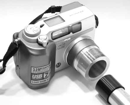
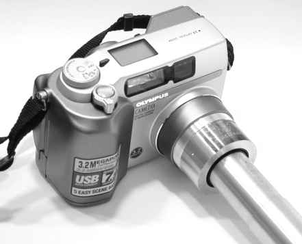
 This adapter I made for a customer with a Nikon Coolpix 5700 digital camera
(reviewed here and
here)
and a Nikon Labophot microscope.
That Nikon camera is unusual because although it is a rather advanced model,
the zoom depends on the lens turret extending various distances in and out of the camera body, like many snapshot cameras.
While the lens hood provides a threaded ring, because of the turret extension, you cannot mount a filter or adapter
directly to those threads; instead you must use a Nikon UR-E8 adapter (shown in the photos), which is essentially a 34mm long step-down tube
from male M53.5-0.75 (mates to lens hood) to female M50x0.75 (for further accessories).
This tube has an ID=51mm and OD=55.75mm, with a stop ridge of 47mm ID at 5.5mm inside of the female threads.
This is the black item in the photos.
The aluminum microscope adapter I made mated to the M50x0.75 thread on the UR-E8 adapter
and received a 23mm (OD) Nikon Labophot microscope eyepiece via a slip fit, overall length of 1 inch.
After taking these specimen photos, I enlarged the 23mm bore to 29.2mm to slip over the external diameter of the Labophot
eyepiece.
This adapter I made for a customer with a Nikon Coolpix 5700 digital camera
(reviewed here and
here)
and a Nikon Labophot microscope.
That Nikon camera is unusual because although it is a rather advanced model,
the zoom depends on the lens turret extending various distances in and out of the camera body, like many snapshot cameras.
While the lens hood provides a threaded ring, because of the turret extension, you cannot mount a filter or adapter
directly to those threads; instead you must use a Nikon UR-E8 adapter (shown in the photos), which is essentially a 34mm long step-down tube
from male M53.5-0.75 (mates to lens hood) to female M50x0.75 (for further accessories).
This tube has an ID=51mm and OD=55.75mm, with a stop ridge of 47mm ID at 5.5mm inside of the female threads.
This is the black item in the photos.
The aluminum microscope adapter I made mated to the M50x0.75 thread on the UR-E8 adapter
and received a 23mm (OD) Nikon Labophot microscope eyepiece via a slip fit, overall length of 1 inch.
After taking these specimen photos, I enlarged the 23mm bore to 29.2mm to slip over the external diameter of the Labophot
eyepiece.
|
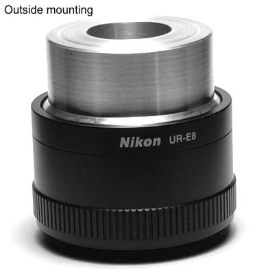
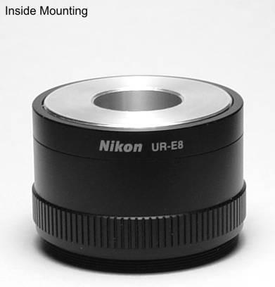 Another unusual feature of this adapter is that it can be screwed inside the UR-E8 adapter, or reversibly outside,
depending on the camera lens turret extension.
This allows the microscope eyepiece a 1.75-inch vertex range relative to the camera, to accommodate various zoom settings
while minimizing vignetting.
The photos to the left show the reversible mounting.
Another unusual feature of this adapter is that it can be screwed inside the UR-E8 adapter, or reversibly outside,
depending on the camera lens turret extension.
This allows the microscope eyepiece a 1.75-inch vertex range relative to the camera, to accommodate various zoom settings
while minimizing vignetting.
The photos to the left show the reversible mounting.
I made a similar large adapter, with Nylon thumbscrew, to adapt a Nikon D70 digital camera with
a 70-300mm zoom lens and 62mm lens thread (M62x0.75), to a Celestron 4060 microscope eyepiece with
a 1.100" outside diameter.
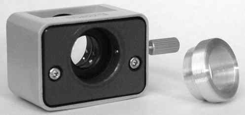
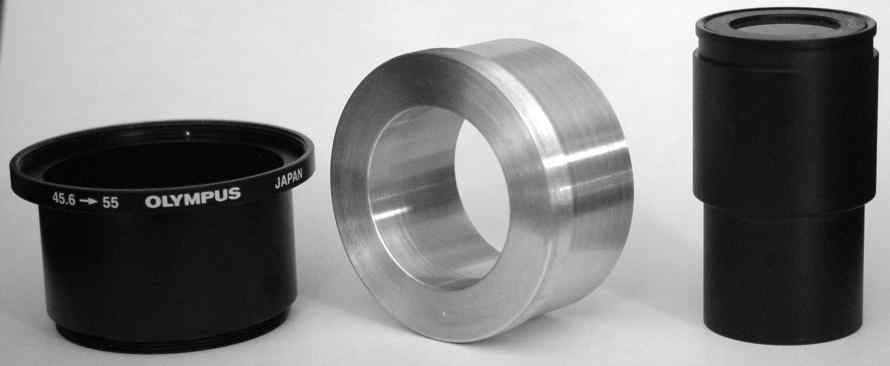
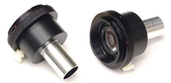
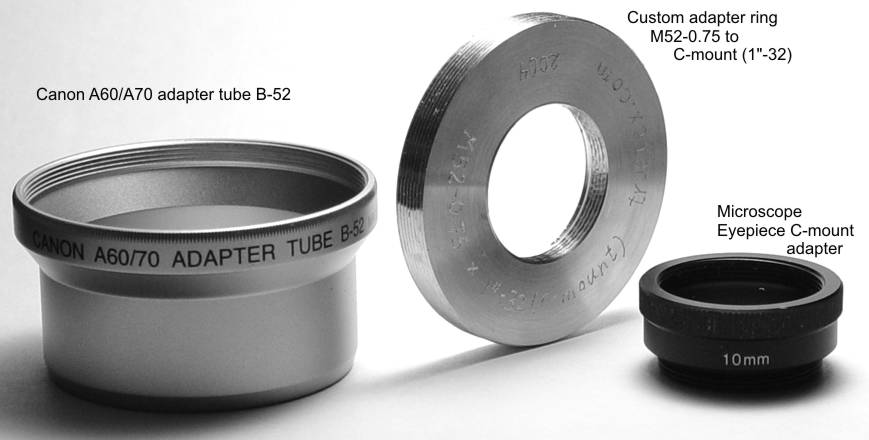 This step-down ring adapter (shown in the center of the photo) I made
for a customer who already had a Canon LA-DC52C step-up adapter (left
of photo) for a Canon A60, A70, A75, or A85 digital camera (similar to the LA-DC52D for the A80 or A95, or the LA-DC52B for the A30 and A40),
which provides an M52x0.75 thread, which was to be mounted to a C-mount (1"-32 thread) adapter (right of photo) on the microscope.
This Canon adapter, like the Nikon one above, provides an offset tube, inside which the lens turret of the camera has room to extend and retract.
Both the inside and outside edges of the ring are threaded, although the photo resolution doesn't resolve all the threads.
This step-down ring adapter (shown in the center of the photo) I made
for a customer who already had a Canon LA-DC52C step-up adapter (left
of photo) for a Canon A60, A70, A75, or A85 digital camera (similar to the LA-DC52D for the A80 or A95, or the LA-DC52B for the A30 and A40),
which provides an M52x0.75 thread, which was to be mounted to a C-mount (1"-32 thread) adapter (right of photo) on the microscope.
This Canon adapter, like the Nikon one above, provides an offset tube, inside which the lens turret of the camera has room to extend and retract.
Both the inside and outside edges of the ring are threaded, although the photo resolution doesn't resolve all the threads.
|
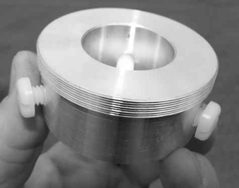
This adapter is different than the others in that instead of an unthreaded sliding fit to a cylindrical microscope eyepiece, the
adapter provides a female thread to connect to C-mount threads on the microscope. It is essentially a 1/4" thick aluminum washer
with threads on the inside and outside edges.
A similar approach would work for the Canon LA-DC58D conversion lens adapter, which provides a 58mm filter thread
for the Canon Powershot G6 camera. Likewise for the LA-DC58 for the Powershot G1 and G2, and the LA-DC58B
for the Powershot G3 and G5.
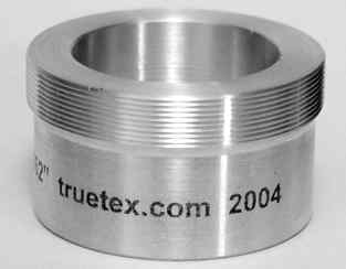 This adapter I made for a customer's Olympus C-4000 camera, which provides a 43mm filter thread mount.
The smooth inside bore slips closely over the eyepiece (1.162" outside diameter) of a Bausch and Lomb inspection microscope.
The height in the photo shows my standard 1-inch overall length for these adapters.
This adapter I made for a customer's Olympus C-4000 camera, which provides a 43mm filter thread mount.
The smooth inside bore slips closely over the eyepiece (1.162" outside diameter) of a Bausch and Lomb inspection microscope.
The height in the photo shows my standard 1-inch overall length for these adapters.
I have also begun including a rubber O-ring with each of the slip-type adapters.
For example, for this adapter with a 1.162" inside diameter,
a standard inch-series #213 Buna-N O-ring (ID=15/16", OD=1-3/16", section=1/8")
fits snugly into the inside diameter without distorting.
This provides a cushion against which one can rest the front of the lens turret
to achieve a near-minimal vertex distance to the eyepiece optics.
To increase the vertex distance, one can insert more of the same O-rings in a stack.
This adapter also required an additional modification (not shown in the photo above or visible in the assembly photo below) to accommodate the turret lens of the camera projecting 0.050" beyond
the end of the Olympus CLA-1 41mm-43mm adapter/extension tube for this camera.
Since the step ending the 43mm female threads inside the Olympus tube was 0.115" deep, a total length of at least 0.165" (0.2" in practice) had to be relieved
inside the threaded end of the adapter, with an inside diameter of 1.575" (40mm) to allow passage of the 1.45" dia extending lens turret.
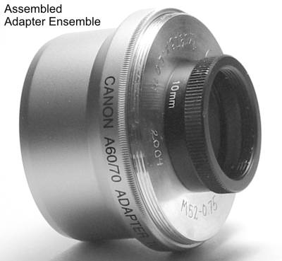
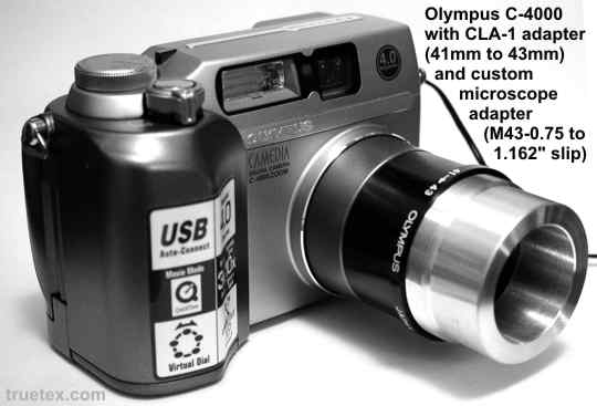 This photo shows the completed assembly, consisting of the Olympus C-4000 camera, Olympus CLA-1 adapter, and custom microscope adapter.
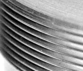 Most camera filter threads have a tiny 0.75mm spacing ("pitch").
This close-up photo shows a threaded section of the C-4000 adapter above.
Threads cut properly on a lathe wiil have a smooth finish and correct profile.
Good-quality threads attach easily to the camera lens, and ensure a secure attachment.
Most camera filter threads have a tiny 0.75mm spacing ("pitch").
This close-up photo shows a threaded section of the C-4000 adapter above.
Threads cut properly on a lathe wiil have a smooth finish and correct profile.
Good-quality threads attach easily to the camera lens, and ensure a secure attachment.
I usually design the threaded length to span about 1/4", which is about 8 to 10 fully threaded turns,
like you see here.
Full engagement to the camera lens typically requires only 2 or 3 careful turns.
Should the initial threads of an adapter ever be damaged, such as by dropping it or accidentally
cross-threading it into the lens, I can repair it on the lathe by simply facing
off a bit of the threaded end, exposing new, undamaged threads at the adapter face.
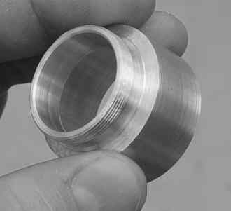
 This custom adapter connects the 37mm filter thread on the customer's camera to an American Optical (AO) inspection
microscope 10X eyepiece having a 1.180" outside diameter.
This adapter is a bit thin, but still strong enough for the mounting task.
In cases where the camera threads happen to be smaller in diameter than the outside of the eyepiece, the adapter uses
a shoulder to step up the body diameter and maintain strength.
This custom adapter connects the 37mm filter thread on the customer's camera to an American Optical (AO) inspection
microscope 10X eyepiece having a 1.180" outside diameter.
This adapter is a bit thin, but still strong enough for the mounting task.
In cases where the camera threads happen to be smaller in diameter than the outside of the eyepiece, the adapter uses
a shoulder to step up the body diameter and maintain strength.
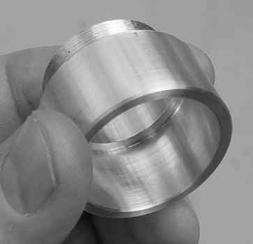
 This photo shows how the eyepiece joins precisely to the adapter with a slip fit.
This provides an accurate axial alignment, which minimizes aberrations and distortions in the photo images.
By having the customer send the actual eyepiece, a very close fit is guaranteed on the first try.
This photo shows how the eyepiece joins precisely to the adapter with a slip fit.
This provides an accurate axial alignment, which minimizes aberrations and distortions in the photo images.
By having the customer send the actual eyepiece, a very close fit is guaranteed on the first try.
These slip fits are designed to be close enough for a "telescoping" fit
between the eyepiece and the adapter, allowing an adjustable range of vertex distance.
The adapter can be fixed on the eyepiece by assembling with a bit of tissue paper or other
thin shim for a tight fit. Or, a bit of white glue or cyanoacrylate (CA) glue ("super glue")
into the gap creates a semi-permanent attachment; since CA glue does not bond strongly to
the oxidized aluminum surfaces of the adapter and eyepiece, the bond is more of a wedge casting than a true glued bond,
and the pieces can be later separated and the glue cleaned off if needed.
We can also add an optional 1/4"-20 threaded hole and Nylon thumbscrew to the adapter as a clamp.
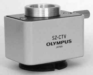
 This custom adapter mounts a Nikon 4500 digital camera with 28mm threads to an Olympus SZ-CTV microscope adapter.
The Olympus adapter provides a cylindrical slip fit with a thumbscrew.
This custom adapter mounts a Nikon 4500 digital camera with 28mm threads to an Olympus SZ-CTV microscope adapter.
The Olympus adapter provides a cylindrical slip fit with a thumbscrew.
 This custom adapter mounts a Nikon Coolpix 950 digital camera with 28mm threads to a Leica microscope eyepiece with 1.126" outside diameter.
This is an unusual adapter in that the eyepiece diameter exceeds the camera threads, requiring a stepped shoulder on the adapter.
This custom adapter mounts a Nikon Coolpix 950 digital camera with 28mm threads to a Leica microscope eyepiece with 1.126" outside diameter.
This is an unusual adapter in that the eyepiece diameter exceeds the camera threads, requiring a stepped shoulder on the adapter.
 This custom adapter mounts an Olympus C-750 digital camera (via the 55mm Olympus CLA-4 adapter tube) to a cylindrical microscope eyepiece.
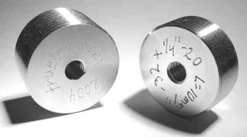 These custom adapters are threaded bushings, with
C-mount (1"-32) threads on the outside, and 1/4"-20 (UNC coarse) threads on the inside.
Lengths are 10mm and 14mm.
The cost of a small item like this by weight roughly equates to gold.
Precision instrumentation is not cheap.
These custom adapters are threaded bushings, with
C-mount (1"-32) threads on the outside, and 1/4"-20 (UNC coarse) threads on the inside.
Lengths are 10mm and 14mm.
The cost of a small item like this by weight roughly equates to gold.
Precision instrumentation is not cheap.
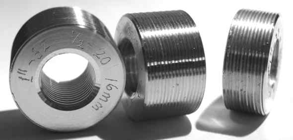 Here the same two adapters are reworked to 1/2"-20 (UNF fine) inside threads, with a third adapter of 16mm length.
 This custom adapter mounts a 37mm camera thread (M37x0.75) to a 1.310" outside diameter cylindrical Bausch & Lomb inspection microscope eyepiece.
Note the use of a fitted O-ring as a cushion for the front of the camera lens, which minimizes the reflex distance and vignetting.
We provide the correct O-ring(s) as needed with the adapter.
This custom adapter mounts a 37mm camera thread (M37x0.75) to a 1.310" outside diameter cylindrical Bausch & Lomb inspection microscope eyepiece.
Note the use of a fitted O-ring as a cushion for the front of the camera lens, which minimizes the reflex distance and vignetting.
We provide the correct O-ring(s) as needed with the adapter.
 This custom adapter mounts a 30mm camera thread (M30x0.75) to a 1.152" outside diameter cylindrical Bausch & Lomb inspection microscope eyepiece.
This mounts a Sony DCR-TRV11 or DCR-TVR27 video camera to the scope.
This custom adapter mounts a 30mm camera thread (M30x0.75) to a 1.152" outside diameter cylindrical Bausch & Lomb inspection microscope eyepiece.
This mounts a Sony DCR-TRV11 or DCR-TVR27 video camera to the scope.
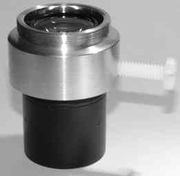
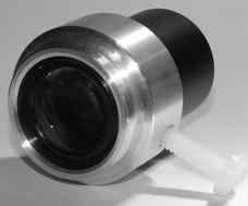
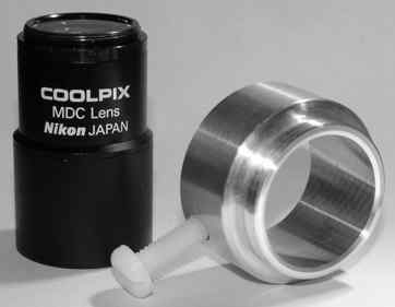 This custom adapter mounts a 37mm camera thread (M37x0.75) to a 1.221" (31mm) outside diameter cylindrical Nikon CoolPix MDC lens (a relay lens for
a Leica MZ16 and other microscopes, also called an MDC-A or MDC-relay, presumably just an acronym for "microscope digital camera" [adapter]).
The close-fitting smooth inside bore of the adapter provides a telescoping mechanism which with the
single nylon clamping screw (1/4"-20 x 1 inch) provides an adjustable vertex distance between camera and microscope.
Male threads (M28x0.75-3mm) at the end of the MDC lens are not used; a fixed step-up ring (28mm to 37mm),
a standard item from photographic suppliers, is an alternative for a fixed-vertex-distance adaptation.
This custom adapter mounts a 37mm camera thread (M37x0.75) to a 1.221" (31mm) outside diameter cylindrical Nikon CoolPix MDC lens (a relay lens for
a Leica MZ16 and other microscopes, also called an MDC-A or MDC-relay, presumably just an acronym for "microscope digital camera" [adapter]).
The close-fitting smooth inside bore of the adapter provides a telescoping mechanism which with the
single nylon clamping screw (1/4"-20 x 1 inch) provides an adjustable vertex distance between camera and microscope.
Male threads (M28x0.75-3mm) at the end of the MDC lens are not used; a fixed step-up ring (28mm to 37mm),
a standard item from photographic suppliers, is an alternative for a fixed-vertex-distance adaptation.
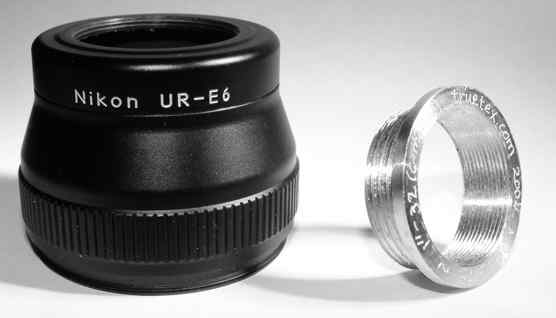 The custom adapter (on the right in the photo) is a threaded-flanged bushing which adapts the 28mm (M28x0.75) female thread of the
Nikon UR-E6 adapter (on the left in the photo, for a Nikon Coolpix 5000 digital camera) to a female C-mount thread (1"-32) for attachment to a microscope lens.
The flange allows one or two O-rings to be inserted to adjust the vertex distance.
This bushing weighed only 3.6 grams, and the inside and outside threads cleared each other by a thickness of less than 1mm.
The finished item was priced at about 3 times the cost of gold by weight.
The custom adapter (on the right in the photo) is a threaded-flanged bushing which adapts the 28mm (M28x0.75) female thread of the
Nikon UR-E6 adapter (on the left in the photo, for a Nikon Coolpix 5000 digital camera) to a female C-mount thread (1"-32) for attachment to a microscope lens.
The flange allows one or two O-rings to be inserted to adjust the vertex distance.
This bushing weighed only 3.6 grams, and the inside and outside threads cleared each other by a thickness of less than 1mm.
The finished item was priced at about 3 times the cost of gold by weight.
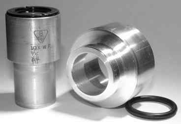
 This custom adapter mounts a Canon EOS Digital Rebel 300D digital SLR with 18-55 EFS lens (58mm camera thread, M58x0.75)
to a 1.154" (29.3mm) outside diamter microscope eyepiece, namely a
Leica Mark X Gemolite Stereo Zoom with 15X W.F. eyepieces.
The three nylon screws (1/4"-20 x 1-inch) allow for vertex distance adjustment.
This custom adapter mounts a Canon EOS Digital Rebel 300D digital SLR with 18-55 EFS lens (58mm camera thread, M58x0.75)
to a 1.154" (29.3mm) outside diamter microscope eyepiece, namely a
Leica Mark X Gemolite Stereo Zoom with 15X W.F. eyepieces.
The three nylon screws (1/4"-20 x 1-inch) allow for vertex distance adjustment.
Topcon SL-5D and SL-6E Slit Lamp
 This custom adapter retrofits Canon and Nikon digital SLRs to the camera port of an ophthalmological instrument, a Topcon slit lamp
(Topcon SL-5D slit lamp and Topcon SL-6E slit lamp).
The camera port in the original design accepted an obsolete Topcon 35mm film camera back.
This photo shows the original bayonet ring mount for the original film camera.
This custom adapter retrofits Canon and Nikon digital SLRs to the camera port of an ophthalmological instrument, a Topcon slit lamp
(Topcon SL-5D slit lamp and Topcon SL-6E slit lamp).
The camera port in the original design accepted an obsolete Topcon 35mm film camera back.
This photo shows the original bayonet ring mount for the original film camera.
 This drawing shows the new adaptation for the Topcon SL-5D and SL-6E slit lamps, consisting of a custom adapter which replaces certain components
in the original bayonet mount, and a stock T-mount adapter for the Canon or Nikon digital SLR.
The custom adapter provides a male T-mount thread (M42x0.75), on which a commercial adapter (T-mount to EOS) is then attached for the camera.
The design works with the original Topcon locking ring to secure the adapter into the instrument.
Adapting in two pieces via an intermediate T-mount thread has several benefits:
it avoids having to machine the more difficult EOS bayonet lens fitting, it allows rotation of the camera on the instrument,
it provides an adjustable vertex distance; and it is compatible with many other T-mount items.
The T-mount-to-EOS ring can be purchased inexpensively off-the-shelf, as well as for a wide variety of other
camera lens standards.
See the detailed mechanical drawing [2.7 MB PDF file] for complete details and specifications.
This drawing shows the new adaptation for the Topcon SL-5D and SL-6E slit lamps, consisting of a custom adapter which replaces certain components
in the original bayonet mount, and a stock T-mount adapter for the Canon or Nikon digital SLR.
The custom adapter provides a male T-mount thread (M42x0.75), on which a commercial adapter (T-mount to EOS) is then attached for the camera.
The design works with the original Topcon locking ring to secure the adapter into the instrument.
Adapting in two pieces via an intermediate T-mount thread has several benefits:
it avoids having to machine the more difficult EOS bayonet lens fitting, it allows rotation of the camera on the instrument,
it provides an adjustable vertex distance; and it is compatible with many other T-mount items.
The T-mount-to-EOS ring can be purchased inexpensively off-the-shelf, as well as for a wide variety of other
camera lens standards.
See the detailed mechanical drawing [2.7 MB PDF file] for complete details and specifications.
 A photo showing the upgraded camera coupler mounted in a Topcon SL-5E slit lamp, ready to receive the digital camera.
The camera coupler locks into the Topcon instrument using the original locking ring and handle seen just below the camera bayonet mount.
A photo showing the upgraded camera coupler mounted in a Topcon SL-5E slit lamp, ready to receive the digital camera.
The camera coupler locks into the Topcon instrument using the original locking ring and handle seen just below the camera bayonet mount.
 A photo showing the Canon 400D (Rebel XTi) digital SLR being mounted on the Topcon SL-5E slit lamp, using the adapter.
Close coupling of the new camera to the instrument maintains parfocality with the eyepiece view, while not interfering with
the observer's chin. The digital camera can be quickly removed and a conventional lens attached for use in ordinary photography.
Besides the Canon 400D (Rebel XTi), the Canon 300D (Digital Rebel), 350D (Digital Rebel XT), 1000D (Digital Rebel XS), and 450D (Digital Rebel XSi) models
are also suitable for this application.
A photo showing the Canon 400D (Rebel XTi) digital SLR being mounted on the Topcon SL-5E slit lamp, using the adapter.
Close coupling of the new camera to the instrument maintains parfocality with the eyepiece view, while not interfering with
the observer's chin. The digital camera can be quickly removed and a conventional lens attached for use in ordinary photography.
Besides the Canon 400D (Rebel XTi), the Canon 300D (Digital Rebel), 350D (Digital Rebel XT), 1000D (Digital Rebel XS), and 450D (Digital Rebel XSi) models
are also suitable for this application.
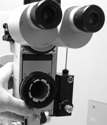
Topcon SL-7E and SL-7F Slit Lamps
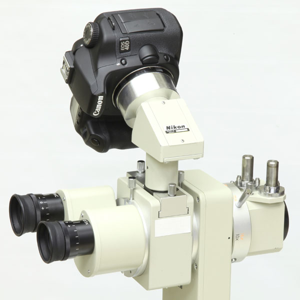
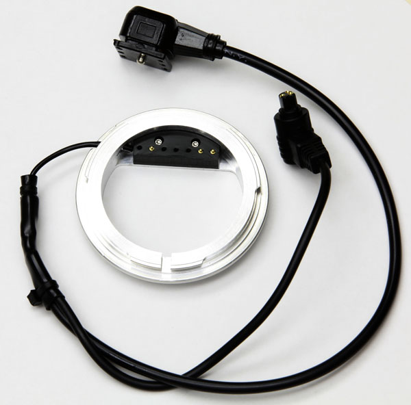
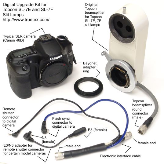 Shown at left is my digital camera upgrade for the Topcon SL-7E and SL-7F slit lamps.
This kit consists of a mechanical bayonet adapter and an electronic interface cable.
The assembly is shown here with a Canon 40D digital camera and the original Topcon beamsplitter.
The adapter is compatible with all Canon digital SLR models.
Shown at left is my digital camera upgrade for the Topcon SL-7E and SL-7F slit lamps.
This kit consists of a mechanical bayonet adapter and an electronic interface cable.
The assembly is shown here with a Canon 40D digital camera and the original Topcon beamsplitter.
The adapter is compatible with all Canon digital SLR models.
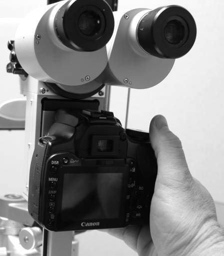
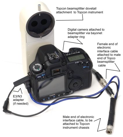 The adapter and digital camera are shown here mounted on the beamsplitter for the Topcon SL-7E slit lamp.
See the installation and operating instructions for more diagrams, photos and details.
Nikon FS-2, FS-3, and FS-3V Slit Lamps
 Nikon made a series of excellent photo slit lamps up until the early 2000s. These were fitted with beamsplitters and camera attachments for Nikon
film SLR bodies. There was also a video camera beamsplitter which is shown in the photo at left.
This beamsplitter I adapted for digital SLRs by (1) fabricating a replacement lens cell to change the optical focal length of the adapter
to an appropriate magnification for the digital SLR sensor, and (2) fabricating a clamp and fitting for the SLR camera mount.
Nikon made a series of excellent photo slit lamps up until the early 2000s. These were fitted with beamsplitters and camera attachments for Nikon
film SLR bodies. There was also a video camera beamsplitter which is shown in the photo at left.
This beamsplitter I adapted for digital SLRs by (1) fabricating a replacement lens cell to change the optical focal length of the adapter
to an appropriate magnification for the digital SLR sensor, and (2) fabricating a clamp and fitting for the SLR camera mount.
 This is the retrofitted beamsplitter, camera adapter, and digital SLR camera assembled to a Nikon FS-2 slit lamp biomicroscope (without
the headrest).
This is the retrofitted beamsplitter, camera adapter, and digital SLR camera assembled to a Nikon FS-2 slit lamp biomicroscope (without
the headrest).
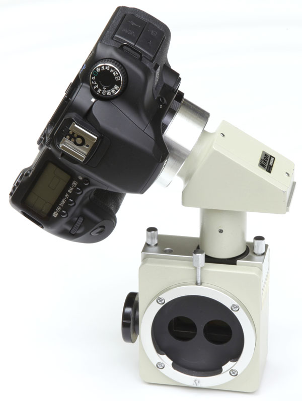
 Nikon also made a drop-down type of beamsplitter attachment for the FS-2/FS-3/FS-3V slit lamps, as shown on the left, similar in principle
to the Topcon SL-7E and SL-7F slit lamps.
The Nikon beamsplitter provided a solenoid-operated mirror and electronic interface for film photography on the slit lamp.
The mirror flip provided 100 percent light to the eyepieces during the examination, while redirecting the same light to the camera during
the moment of photographic exposure. This avoids losing light in the 50/50 or 70/30 division in the usual prismatic or half-mirror beamsplitter.
I have seen these beamsplitters in four various configurations for different camera body types:
(1) with a standard Nikon F bayonet, and hard-wired cables providing the standard Nikon remote shutter connector (10-pin round) and standard PC flash-sync connector;
(2) also with Nikon F bayonet but an 8-pin Hirose RP6 receptacle connector (no longer made) for the shutter and flash sync signals;
(3) like the previous but with a 10-pin Hirose RP6 connector;
and (4) with an unusual Nikon bayonet mount (which is not the Nikon F mount) for scientific instrumentation
having pogo-pin connections, similar to what is used on the Topcon TRC-50EX and TRC-50DX retinal cameras (for which Nikon apparently
made the 35mm film camera bodies).
The first beamsplitter configuration with its Nikon-F bayonet can accept a Nikon digital SLR without modification,
if the digital SLR model is one of the mid-range or high-end models that provide the 10-pin type of connector.
To use other Nikon digital SLR models providing different remote connectors requires splicing in the appropriate connector.
The bayonet on the second and third beamsplitter configuration also fits a Nikon digital SLR directly, but the electronics must be disassembled and modified
to replace the obsolete Hirose connection with cables and signals to fit the DSLR shutter and flash sync interfaces.
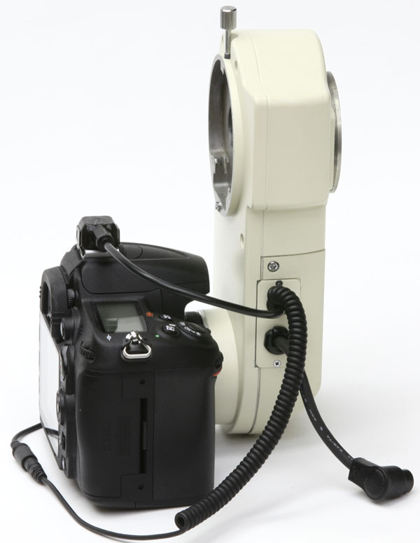
The fourth beamsplitter configuration requires both mechanical and electronic adaptations such as shown on the left, where I replaced the instrumentation
bayonet with a custom T-mount lens fitting, and I added an electronic interface and cabling for shutter remote and flash sync,
such as for the Nikon D7000 shown. The T-mount adaptation can also be applied to the Nikon F configuration to allow use with
Canon and other non-Nikon digital SLRs via hot-shoe connector.
Nikon also made a drop-down type of beamsplitter attachment for the FS-2/FS-3/FS-3V slit lamps, as shown on the left, similar in principle
to the Topcon SL-7E and SL-7F slit lamps.
The Nikon beamsplitter provided a solenoid-operated mirror and electronic interface for film photography on the slit lamp.
The mirror flip provided 100 percent light to the eyepieces during the examination, while redirecting the same light to the camera during
the moment of photographic exposure. This avoids losing light in the 50/50 or 70/30 division in the usual prismatic or half-mirror beamsplitter.
I have seen these beamsplitters in four various configurations for different camera body types:
(1) with a standard Nikon F bayonet, and hard-wired cables providing the standard Nikon remote shutter connector (10-pin round) and standard PC flash-sync connector;
(2) also with Nikon F bayonet but an 8-pin Hirose RP6 receptacle connector (no longer made) for the shutter and flash sync signals;
(3) like the previous but with a 10-pin Hirose RP6 connector;
and (4) with an unusual Nikon bayonet mount (which is not the Nikon F mount) for scientific instrumentation
having pogo-pin connections, similar to what is used on the Topcon TRC-50EX and TRC-50DX retinal cameras (for which Nikon apparently
made the 35mm film camera bodies).
The first beamsplitter configuration with its Nikon-F bayonet can accept a Nikon digital SLR without modification,
if the digital SLR model is one of the mid-range or high-end models that provide the 10-pin type of connector.
To use other Nikon digital SLR models providing different remote connectors requires splicing in the appropriate connector.
The bayonet on the second and third beamsplitter configuration also fits a Nikon digital SLR directly, but the electronics must be disassembled and modified
to replace the obsolete Hirose connection with cables and signals to fit the DSLR shutter and flash sync interfaces.
The fourth beamsplitter configuration requires both mechanical and electronic adaptations such as shown on the left, where I replaced the instrumentation
bayonet with a custom T-mount lens fitting, and I added an electronic interface and cabling for shutter remote and flash sync,
such as for the Nikon D7000 shown. The T-mount adaptation can also be applied to the Nikon F configuration to allow use with
Canon and other non-Nikon digital SLRs via hot-shoe connector.
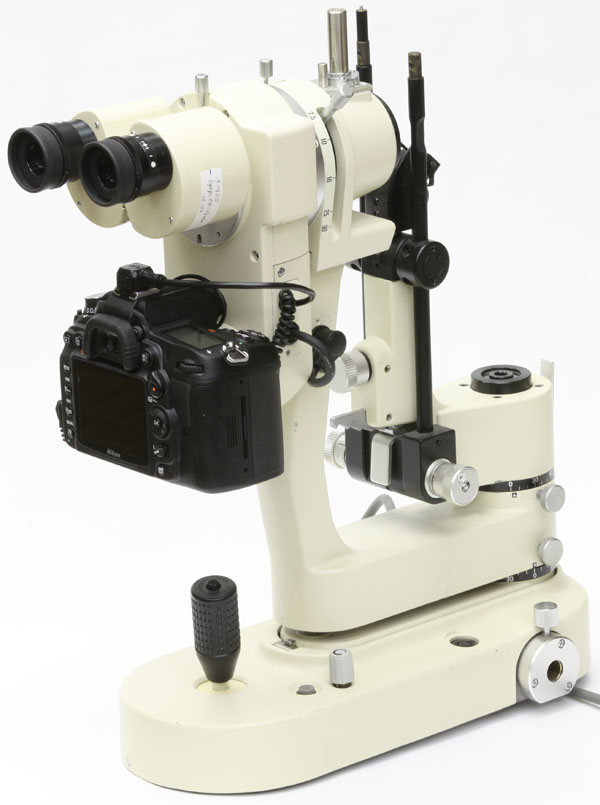 Here is the retrofitted beamsplitter and custom camera adapter assembled to a Nikon FS-3V slit lamp biomicroscope (without
the headrest, illumination tower, and flash power supply), shown with a Nikon D7000 DSLR for digital photography.
Nikon used infinity-optics and stackable-dovetail-accessory principles as introduced by Zeiss.
This is a superb instrument with built-in flash for slit-lamp photography of the highest quality, originally in the film era but
now in digital technology.
In my opinion the zoom optics and integrated flash make this the best photographic slit lamp ever made, rivalled only by the
current Haag-Streit BX900.
Too bad Nikon did not succeed in this business, and discontinued making slit lamps and retinal cameras in the early 2000s.
The $20K price in those days was extremely costly for a clinical instrument, which explains why this could not have been a big seller
and is rarely found now.
Here is the retrofitted beamsplitter and custom camera adapter assembled to a Nikon FS-3V slit lamp biomicroscope (without
the headrest, illumination tower, and flash power supply), shown with a Nikon D7000 DSLR for digital photography.
Nikon used infinity-optics and stackable-dovetail-accessory principles as introduced by Zeiss.
This is a superb instrument with built-in flash for slit-lamp photography of the highest quality, originally in the film era but
now in digital technology.
In my opinion the zoom optics and integrated flash make this the best photographic slit lamp ever made, rivalled only by the
current Haag-Streit BX900.
Too bad Nikon did not succeed in this business, and discontinued making slit lamps and retinal cameras in the early 2000s.
The $20K price in those days was extremely costly for a clinical instrument, which explains why this could not have been a big seller
and is rarely found now.
If you are fortunate to own one of these fine Nikon instruments with a film camera, please contact me to retrofit it to digital photography
and preserve its value and enduring worth.
Topcon TRC-50EX and TRC-50X Retinal Cameras (Upper Port Digital Camera Adapter)
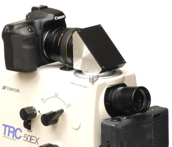 This is an updated version of the upper-port adapter for the Topcon TRC-50EX retinal camera.
For more photos and technical details, see the installation and operating instructions.
You can also read the original TRC-50EX instruction manual [4 MB PDF file, 71 pages].
I also make a Topcon TRC-50X digital adapter (technical details and ordering); you can also download the original
TRC-50X instruction manual [6 MB PDF file, 46 pages].
See a sample digital retinal photo [1.2 MB JPEG image] taken on a Topcon TRC-50X with a Canon T2i digital SLR camera
using this adapter.
This is an updated version of the upper-port adapter for the Topcon TRC-50EX retinal camera.
For more photos and technical details, see the installation and operating instructions.
You can also read the original TRC-50EX instruction manual [4 MB PDF file, 71 pages].
I also make a Topcon TRC-50X digital adapter (technical details and ordering); you can also download the original
TRC-50X instruction manual [6 MB PDF file, 46 pages].
See a sample digital retinal photo [1.2 MB JPEG image] taken on a Topcon TRC-50X with a Canon T2i digital SLR camera
using this adapter.
 This adapter couples a Topcon TRC-50EX retinal camera to a Canon 400D digital SLR.
It is complex, consisting of optical, mechanical, and electrical components.
See the installation and operating instructions for more diagrams, photos and details.
Five optical elements in two groups resize and relocate the instrument exit pupil at a suitable distance for a relay lens,
which in turn refocuses the image at a size to match the camera's digital sensor, which is 0.6 the size of the original 35mm film
intended for the instrument. Mechanical components maintain a rigid positioning of the optics, as well as axial and rotational
adjustments for focusing and alignment. The electronic interface cable (not shown) operates the digital camera synchronously
with the instrument triggers.
This adapter couples a Topcon TRC-50EX retinal camera to a Canon 400D digital SLR.
It is complex, consisting of optical, mechanical, and electrical components.
See the installation and operating instructions for more diagrams, photos and details.
Five optical elements in two groups resize and relocate the instrument exit pupil at a suitable distance for a relay lens,
which in turn refocuses the image at a size to match the camera's digital sensor, which is 0.6 the size of the original 35mm film
intended for the instrument. Mechanical components maintain a rigid positioning of the optics, as well as axial and rotational
adjustments for focusing and alignment. The electronic interface cable (not shown) operates the digital camera synchronously
with the instrument triggers.
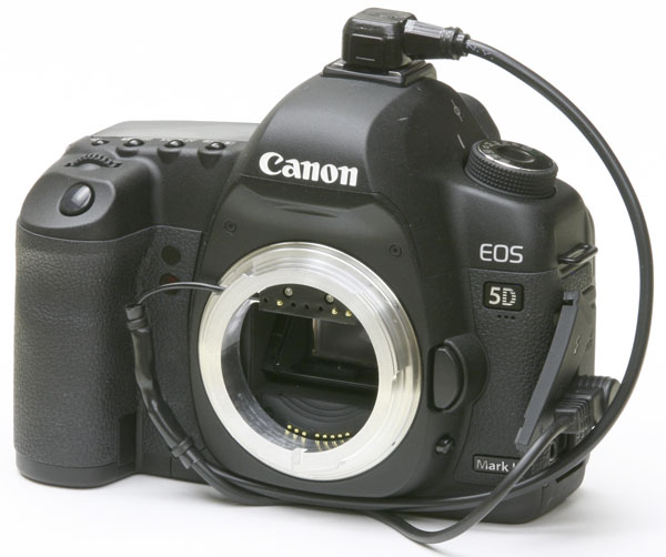
 This photo shows the adapter mounted on a Canon 400D digital SLR camera.
Besides the 5 optical elements, the adapter consists of 4 custom and 2 stock mechanical assemblies.
This photo shows the adapter mounted on a Canon 400D digital SLR camera.
Besides the 5 optical elements, the adapter consists of 4 custom and 2 stock mechanical assemblies.
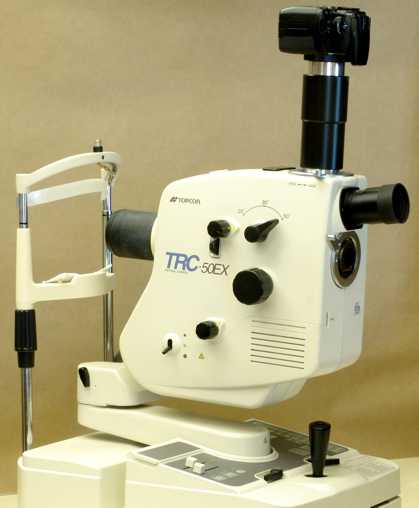 Here's the adapter and camera mounted on the Topcon TRC-50EX.
We have used the upper port which the Topcon TRC-50EX provides for mounting an accessory camera.
To take a photo, the operator pushes a button on the instrument joystick to trigger a synchronized series of events:
First, an instrument mirror flips to redirect the image from the viewfinder eyepiece to the upper camera.
Second, the instrument sends an electronic signal to the digital camera to open the its shutter.
Third, when the digital camera has opened its shutter, it returns an electronic signal to the instrument to fire the flash illumination.
Fourth, the instrument fires the flash.
Fifth, the camera shutter closes.
Finally, the instrument returns the mirror to the viewfinder path.
The custom cable which connects the digital SLR's shutter release and flash sync to the Topcon instrument is not shown here.
Here's the adapter and camera mounted on the Topcon TRC-50EX.
We have used the upper port which the Topcon TRC-50EX provides for mounting an accessory camera.
To take a photo, the operator pushes a button on the instrument joystick to trigger a synchronized series of events:
First, an instrument mirror flips to redirect the image from the viewfinder eyepiece to the upper camera.
Second, the instrument sends an electronic signal to the digital camera to open the its shutter.
Third, when the digital camera has opened its shutter, it returns an electronic signal to the instrument to fire the flash illumination.
Fourth, the instrument fires the flash.
Fifth, the camera shutter closes.
Finally, the instrument returns the mirror to the viewfinder path.
The custom cable which connects the digital SLR's shutter release and flash sync to the Topcon instrument is not shown here.
Topcon TRC-50EX Retinal Camera (Rear Port Digital Camera Adapter)
 A later design of mine shown here for the Topcon TRC-50EX rear port
is a bayonet adapter with gold "pogo pin" connection (also called a "hot shoe" connection)
for electronic interface to the Topcon instrument.
The pins and housing for the electronic interface are a custom, precision design and assembly fitted
to match the original dimensions.
One side provides the mechanical Canon bayonet attachment, and the other the Topcon bayonet.
See the mechanical drawing [572 KB PDF file, 1 page] for details.
This adapter also fits the latest Topcon TRC-50DX retinal cameras, which use the same rear port interface, but
an extension on the port is required, with a matching extension inserted in the viewfinder, to avoid interference
between the digital camera body and the case on the TRC-50DX (which unfortunately projects out further than on the TRC-50EX).
A later design of mine shown here for the Topcon TRC-50EX rear port
is a bayonet adapter with gold "pogo pin" connection (also called a "hot shoe" connection)
for electronic interface to the Topcon instrument.
The pins and housing for the electronic interface are a custom, precision design and assembly fitted
to match the original dimensions.
One side provides the mechanical Canon bayonet attachment, and the other the Topcon bayonet.
See the mechanical drawing [572 KB PDF file, 1 page] for details.
This adapter also fits the latest Topcon TRC-50DX retinal cameras, which use the same rear port interface, but
an extension on the port is required, with a matching extension inserted in the viewfinder, to avoid interference
between the digital camera body and the case on the TRC-50DX (which unfortunately projects out further than on the TRC-50EX).
 This adapter works with the full-frame Canon 5D Mark II digital SLR to replace the Topcon MT-10 film camera which
originally took photographs on the instrument.
The adapter provides an attachment at a parfocal distance so that the digital camera is mechanically and
optically equal to the film camera being replaced.
Parfocality in this adapter is crucial, since the instrument's original eyepiece viewfinder is retained.
The required distances leave only a few millimeters of space within which to machine both the bayonet
mechanisms and the electronics assembly.
This adapter works with the full-frame Canon 5D Mark II digital SLR to replace the Topcon MT-10 film camera which
originally took photographs on the instrument.
The adapter provides an attachment at a parfocal distance so that the digital camera is mechanically and
optically equal to the film camera being replaced.
Parfocality in this adapter is crucial, since the instrument's original eyepiece viewfinder is retained.
The required distances leave only a few millimeters of space within which to machine both the bayonet
mechanisms and the electronics assembly.
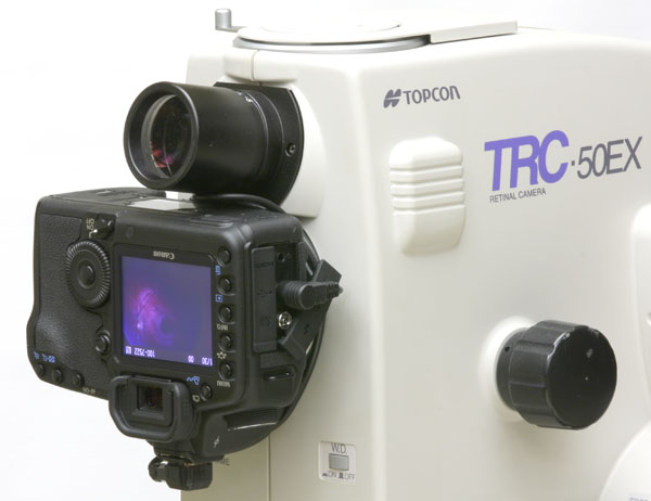 This photo shows the digital camera mounted on the instrument with the adapter. The instrument joystick triggers
the digital camera shutter via the Canon remote connector, and the Canon flash sync terminal in turn fires the
Topcon instrument flash. Photos are immediately reviewable on the camera as shown, or may be automatically transferred
and displayed on an attached PC via tethering software.
This photo shows the digital camera mounted on the instrument with the adapter. The instrument joystick triggers
the digital camera shutter via the Canon remote connector, and the Canon flash sync terminal in turn fires the
Topcon instrument flash. Photos are immediately reviewable on the camera as shown, or may be automatically transferred
and displayed on an attached PC via tethering software.
 To provide parfocality, mounting of the digital camera must be very close to the instrument.
The Canon 5D digital SLR body just barely clears any interference with the Topcon exterior.
Other brands and models of digital camera bodies will not fit here, because they have features such
as a built-in flash which project too far forward and would not permit this close adaptation.
To provide parfocality, mounting of the digital camera must be very close to the instrument.
The Canon 5D digital SLR body just barely clears any interference with the Topcon exterior.
Other brands and models of digital camera bodies will not fit here, because they have features such
as a built-in flash which project too far forward and would not permit this close adaptation.
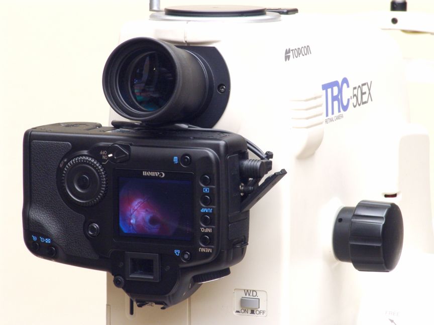 The camera is mounted upside down to avoid mechanical interference
with the original viewfinder, and to yield an upright image from the Topcon instrumentation optics, which are inverted relative to
an ordinary SLR camera lens..
The camera is mounted upside down to avoid mechanical interference
with the original viewfinder, and to yield an upright image from the Topcon instrumentation optics, which are inverted relative to
an ordinary SLR camera lens..
The adapter works with both the Canon 5D and the Canon 5D Mark II model camera bodies.
The digital camera readily detaches and is then usable for ordinary photography by attaching a conventional SLR lens,
or to switch to a different instrument.
See also the installation instructions for this product.
Kowa fx-50R Retinal Camera (Rear Port Digital Camera Adapter)
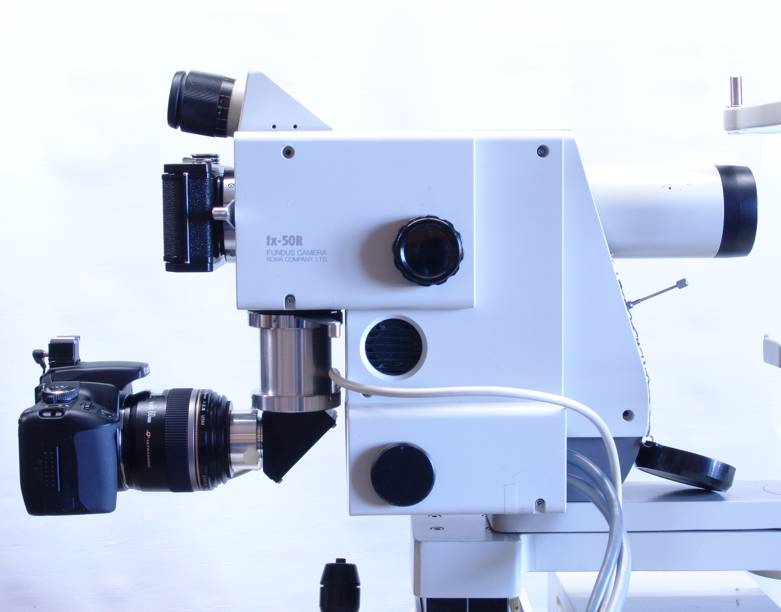 This adapter, seen on the lower port of a Kowa fx-50R retinal camera where a Polaroid camera used to attach,
fits a Canon digital camera with a macro lens to the instrument.
The smaller original 35mm film camera body is seen on the rear port, above which is the viewfinding eyepiece.
Kowa's instrument design is quite suitable for digital conversion because the
viewfinder is a fixed and separate part of the instrument, instead of being incorporated into the 35mm film or Polaroid film camera backs.
This adapter, seen on the lower port of a Kowa fx-50R retinal camera where a Polaroid camera used to attach,
fits a Canon digital camera with a macro lens to the instrument.
The smaller original 35mm film camera body is seen on the rear port, above which is the viewfinding eyepiece.
Kowa's instrument design is quite suitable for digital conversion because the
viewfinder is a fixed and separate part of the instrument, instead of being incorporated into the 35mm film or Polaroid film camera backs.
The diagonal mirror on the digital adapter orients the camera to clear of the rest of the instrument, and unmirrors the
image which was previously mirrored inside the instrument.
A single lens element in the adapter acts as a field lens to avoid vignetting in the macro imaging technique.
A custom electronic cable inserts between the original connectors to intercept the joystick pushbutton signal,
remotely triggering the digital camera shutter instead of the instrument;
the cable also forwards the digital camera flash sync signal to the instrument to triggers the instrument flash.
The adapter provides two swivel adjustment mechanisms, one on each side of the diagonal, with setscrews and
thumbscrews for adjustment and locking.
This permits the adapter to pivot to the operator's right or left while still producing an upright digital image.
This left or right pivot moves the digital camera out of the photographer's way, although it is not then so convenient for
reviewing photos on the camera's display. Tethering the camera to a PC display is thus desirable with the pivoted orientations.
This adapter also fits the newer Kowa fx-500 (Kowa fx-500S) retinal cameras.
Technical details and more photos are available in the installation and use instructions.
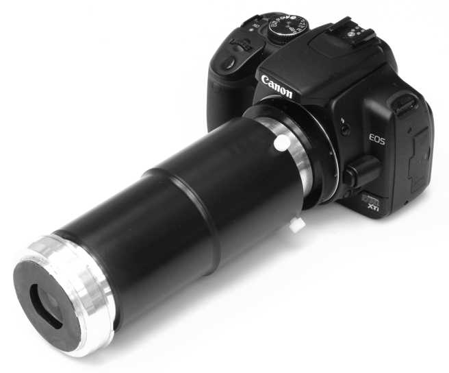
Kowa RC-2 Handheld Retinal Camera (Rear Port Digital Camera Adapter)
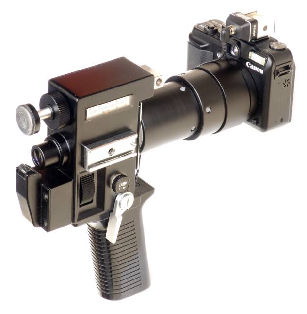 This adapter converts an unusual retinal camera, which is portable and handheld, for digital photography.
The instrument provides a steady illumination lamp for examination of the patient's retina as well as a xenon flash lamp for photography.
Light from these lamps exits the prism, just under the objective lens, where it enters the pupil of the subject eye at a steep angle
to avoid a corneal reflection back towards the observer's point of view.
The original compact camera body used 35mm film in direct projection and was attached with a
locking rail mechanism. The film camera also provided a reflex viewfinder.
To adapt this instrument for digital photography, we first remove the film camera
and replace it with a custom-machined threaded bushing that fits around the exit lens and is attached with screws
in place of those that held the rails. Then onto this thread we can attach a 3-part adapter consisting of a 30mm
eyepiece barrel, eyepiece adapter, and stock conversion lens adapter tube. A 30mm wide-field eyepiece with 22mm field number is chosen
to afocalize the image for a Canon G10 (or G11 or G12) digital camera, which provides the full field of view of the original instrument.
The eyepiece also provides a very long exit pupil that reaches into the very deep entrance pupil of the Canon lens on this type of camera.
White Nylon setscrews provide rotational calibration of the camera orientation,
and axial alignment of the camera entrance pupil.
This adapter converts an unusual retinal camera, which is portable and handheld, for digital photography.
The instrument provides a steady illumination lamp for examination of the patient's retina as well as a xenon flash lamp for photography.
Light from these lamps exits the prism, just under the objective lens, where it enters the pupil of the subject eye at a steep angle
to avoid a corneal reflection back towards the observer's point of view.
The original compact camera body used 35mm film in direct projection and was attached with a
locking rail mechanism. The film camera also provided a reflex viewfinder.
To adapt this instrument for digital photography, we first remove the film camera
and replace it with a custom-machined threaded bushing that fits around the exit lens and is attached with screws
in place of those that held the rails. Then onto this thread we can attach a 3-part adapter consisting of a 30mm
eyepiece barrel, eyepiece adapter, and stock conversion lens adapter tube. A 30mm wide-field eyepiece with 22mm field number is chosen
to afocalize the image for a Canon G10 (or G11 or G12) digital camera, which provides the full field of view of the original instrument.
The eyepiece also provides a very long exit pupil that reaches into the very deep entrance pupil of the Canon lens on this type of camera.
White Nylon setscrews provide rotational calibration of the camera orientation,
and axial alignment of the camera entrance pupil.
Viewfinding is now done digitally on the LCD screen of the camera.
We used the Canon G10 (or G11 or G12) camera rather than a digital SLR because of the weight requirements of the handheld design,
and the mechanical interference that parfocal mounting of an SLR would have imposed.
The adapter components are all aluminum or Delrin for minimal weight.
Part of the economy of the original design was to route the 300 volt xenon flash trigger through
the film camera, which must now be isolated from the digital camera electronics.
A "safe sync" adapter connects the flash synchronization signal from the Canon camera to the high-voltage PC-sync
connector on the instrument.
Haag-Streit BM 900 Slit Lamp Digital Camera Adapter
 This device adapts a Canon digital SLR (or other T-mount adaptable SLR body)
to the eyetube of a Haag-Streit BM 900 slit lamp,
providing digital photography through this 50-year-old classic instrument design.
The eyepieces of this instrument are of an older Huygenian design no longer used much for microscopy,
requiring an unusual adapter geometry. The barrel diameter and flange distance of this Haag-Streit model are also non-standard,
requiring customization of the adapter tube.
A telescoping lens cell with thumbscrew lock allows for parfocal calibration to the instrument's focal plane with inscribed crop
of the full field of view, or the crop factor can be adjusted with consequent non-parfocal operation.
The adapter body is machined from black Delrin; the narrow barrel is machined from aluminum with flat black paint inside.
This device adapts a Canon digital SLR (or other T-mount adaptable SLR body)
to the eyetube of a Haag-Streit BM 900 slit lamp,
providing digital photography through this 50-year-old classic instrument design.
The eyepieces of this instrument are of an older Huygenian design no longer used much for microscopy,
requiring an unusual adapter geometry. The barrel diameter and flange distance of this Haag-Streit model are also non-standard,
requiring customization of the adapter tube.
A telescoping lens cell with thumbscrew lock allows for parfocal calibration to the instrument's focal plane with inscribed crop
of the full field of view, or the crop factor can be adjusted with consequent non-parfocal operation.
The adapter body is machined from black Delrin; the narrow barrel is machined from aluminum with flat black paint inside.
 Here is the Haag-Streit BM 900 adapter mounted on a Canon 40D digital SLR camera.
To take a photograph, the examiner replaces one of the eyepieces with the adapted camera.
Framing and focusing are available through the other binocular eyepiece, or through the viewfinder of the digital camera.
An optional foot switch provide hands-free shutter operation.
The design is based on the T-mount thread mount, which through an inexpensive bayonet component allows use with any make or model of digital SLR camera.
Here is the Haag-Streit BM 900 adapter mounted on a Canon 40D digital SLR camera.
To take a photograph, the examiner replaces one of the eyepieces with the adapted camera.
Framing and focusing are available through the other binocular eyepiece, or through the viewfinder of the digital camera.
An optional foot switch provide hands-free shutter operation.
The design is based on the T-mount thread mount, which through an inexpensive bayonet component allows use with any make or model of digital SLR camera.
Topcon TRC-NW6 Non-Mydriatic Retinal Camera Digital Adapter
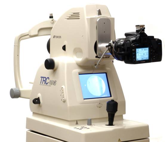 This adapter upgrades a Topcon non-mydriatic retinal camera to use a Canon digital SLR camera instead of the
Polaroid or 35mm film camera originally fitted.
The electrical interface uses an interpolation technique, whereby the internal circuitry is
modified to intercept the joystick trigger signal and send it through the digital camera
before processing by the instrument, thus synchronizing the otherwise incompatible timing.
This adapter upgrades a Topcon non-mydriatic retinal camera to use a Canon digital SLR camera instead of the
Polaroid or 35mm film camera originally fitted.
The electrical interface uses an interpolation technique, whereby the internal circuitry is
modified to intercept the joystick trigger signal and send it through the digital camera
before processing by the instrument, thus synchronizing the otherwise incompatible timing.
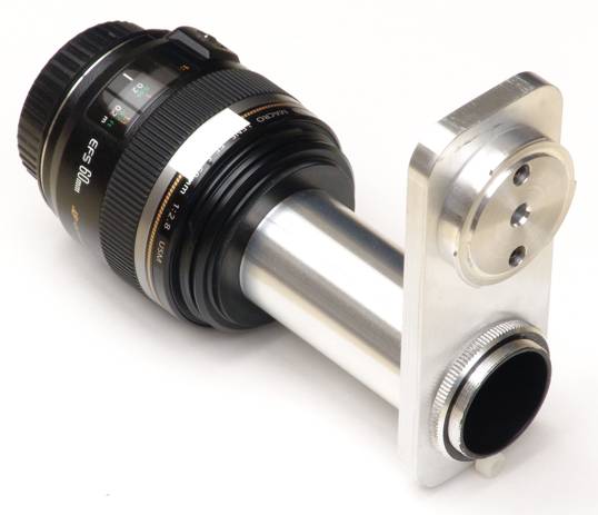 This adapter requires much in the way of precise mechanical improvisation since the instrument uses two
simultaneous connections for electrical versus mechanical connection, as opposed to earlier Topcon models
which tended to incorporate them into one connection.
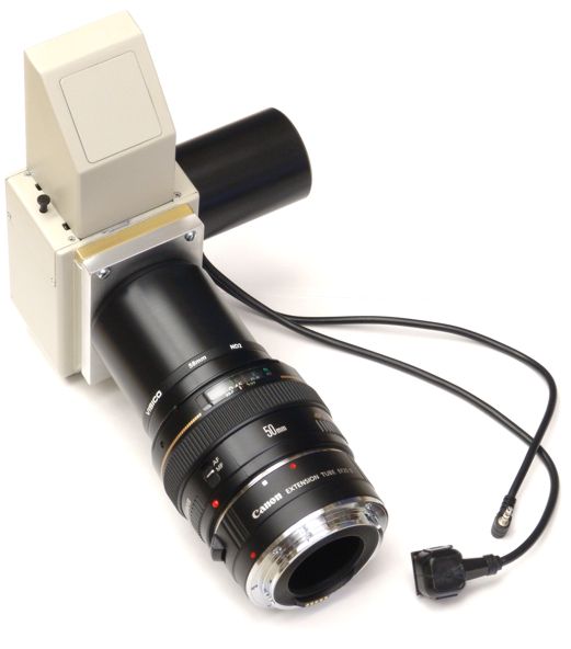
The optical design exploits the macro principle available on certain Canon lenses, which fills the
digital frame with the instrument image while permitting parfocal calibration to the infrared imaging
system of the non-mydriatic viewfinder.
This adapter requires much in the way of precise mechanical improvisation since the instrument uses two
simultaneous connections for electrical versus mechanical connection, as opposed to earlier Topcon models
which tended to incorporate them into one connection.
The optical design exploits the macro principle available on certain Canon lenses, which fills the
digital frame with the instrument image while permitting parfocal calibration to the infrared imaging
system of the non-mydriatic viewfinder.
More photos and technical details are found in the installation and operating instructions for the Topcon TRC-NW6 digital adapter
here.
See a sample retinal image [2269 x 2269 pixels, JPEG 1.4MB] taken
with the Topcon TRC-NW6 using the adapter with a Canon 40D digital camera.
Topcon TRC-NW3 Non-Mydriatic Retinal Camera
 This custom-modified attachment for the Topcon TRC-NW3 retinal camera upgrades the system for
digital photography.
This Topcon model is older than the Topcon TRC-NW6 above, but performs very well and is an excellent
base for a digitally upgraded system.
See the Topcon TRC-NW3 digital upgrade instruction manual for more technical details and photos.
You can also read the original Topcon TRC-NW3 instruction manual [6 MB PDF file, 31 pages].
This custom-modified attachment for the Topcon TRC-NW3 retinal camera upgrades the system for
digital photography.
This Topcon model is older than the Topcon TRC-NW6 above, but performs very well and is an excellent
base for a digitally upgraded system.
See the Topcon TRC-NW3 digital upgrade instruction manual for more technical details and photos.
You can also read the original Topcon TRC-NW3 instruction manual [6 MB PDF file, 31 pages].
Topcon TRC-50VT Retinal Camera
 This adapter kit converts a Topcon TRC-50VT retinal camera (also known as a fundus camera) from the original
film camera back to use a Canon EOS digital SLR camera.
The kit consists of:
This adapter kit converts a Topcon TRC-50VT retinal camera (also known as a fundus camera) from the original
film camera back to use a Canon EOS digital SLR camera.
The kit consists of:
- A mechanical adapter to mount the Canon digital camera on the Topcon instrument in a precisely parfocal, axially centered position.
- A modified breech ring that replaces the original Topcon ring, which avoids the mechanical interference of the flash "nose" of
certain Canon SLR models with the instrument.
- An neutral-density filter for the Topcon instrument, which reduces the instrument's flash intensity to compensate for the Canon digital SLR's improved light sensitivity.
- A flash synchronization adapter cable, which triggers the Topcon instrument flash in synchronization with the Canon digital camera shutter.
This cable adapts the Canon digital camera flash trigger signal to the DB-15 connector provided on the Topcon TRC-50VT, which was originally intended for a Polaroid camera.
|
See the mechanical drawing [700 KB PDF file] for a detailed view of the adapted camera mounting.
There are 3 options I build for the Topcon TRC-50VT:
- Direct projection to an APS-frame Canon or Nikon digital SLR, such as the Canon 50D,
- Direct projection to a full-frame Canon 5D or 5D Mark II on the rear port, and
- Relay lens to a APS-frame Canon or Nikon digital SLR on the upper port.
Option (1) imposes an 0.6X crop factor, so you lose some of the top and bottom
of the image, both in viewing and in imaging. Options (2) and (3)
don't crop, they show the full frame.
Options (1) and (2) mount the digital camera on the rear port, close
to the instrument like the original film camera. Option (3) mounts
the digital camera above the top of the instrument on the upper port,
similar to the optional Polaroid or TV attachments Topcon originally
sold for the instrument.
Options (1) and (2) show an inverted preview, which you either get
used to, or use my inverting
Canon viewfinder magnifier,
which adds 4 inches
of length the rear of the camera. These options also eliminate the
Topcon viewfinder as a consequence of using the rear port. The Canon
viewfinder is a focusing-screen type with a beamsplitter for autofocus
and exposure metering, which is necessarily smaller and less bright
compared to the original Topcon viewfinder eyepiece with its near-100
percent transmission. You typically have to boost the steady illumination
to compensate with difficult subject eyes compared to the Topcon film camera
viewfinder, which adds another difficulty factor in itself to marginally
viewable subjects. Viewfinding for fluorescein angiography (FA) is
thus hardly possible, since the views are so dim even in the Topcon viewfinder.
Option (3) retains the Topcon film camera for viewfinding, with the
digital camera acting as an image recorder only. This configuration
performs with the same superb clinical convenience of the original design.
The chief disadvantage is the higher cost. A secondary disadvantage is
that it relies on the mirror-flip mechanism for the upper port, which
has proven trouble-prone in the aging Topcon film-based instruments.
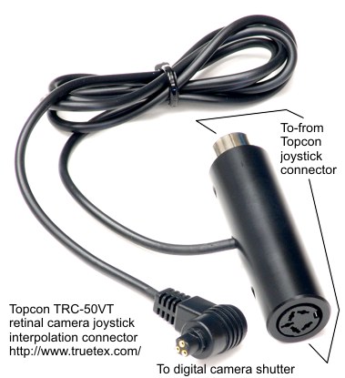 The complete adaptation requires not only mechanical and optical devices, but an
electronic interface as well, since the old film cameras used a different signaling and
synchronization method than today's digital cameras.
At left is a photo of the joystick interpolation connector I designed for this pupose,
consisting of a custom machined housing
holding the appropriate connectors and containing an electronic chip and wiring..
This device inserts between the plug and socket connecting the Topcon joystick to the Topcon controller,
and provides a new cable to the digital camera shutter remote connector.
This allows the digital camera to shoot a picture whenever the joystick button is pressed.
The camera remote connector shown is for a Canon N3 type; Canon E3 or Nikon 10-pin connectors
are also supported by the design.
Flash synchronization of the instrument to the digital camera is provided by a separate electronic interface using a similar arrangement.
For more details, see the installation instructions for the
interpolation cable.
The complete adaptation requires not only mechanical and optical devices, but an
electronic interface as well, since the old film cameras used a different signaling and
synchronization method than today's digital cameras.
At left is a photo of the joystick interpolation connector I designed for this pupose,
consisting of a custom machined housing
holding the appropriate connectors and containing an electronic chip and wiring..
This device inserts between the plug and socket connecting the Topcon joystick to the Topcon controller,
and provides a new cable to the digital camera shutter remote connector.
This allows the digital camera to shoot a picture whenever the joystick button is pressed.
The camera remote connector shown is for a Canon N3 type; Canon E3 or Nikon 10-pin connectors
are also supported by the design.
Flash synchronization of the instrument to the digital camera is provided by a separate electronic interface using a similar arrangement.
For more details, see the installation instructions for the
interpolation cable.
Other model Canon cameras such as the Digital Rebel series (original, XT, XTi, XS, and XSi models, also known
as the 300D, 350D, 400D, 1000D, and 450D respectively), and
the 10D/20D/30D/40D/50D series, are compatible with options (1) and (3).
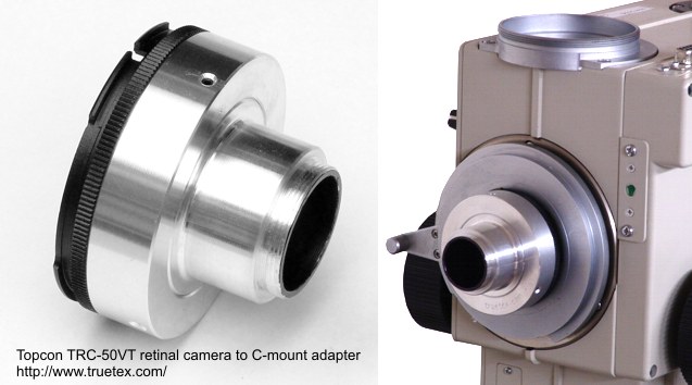 This adapter converts the rear port of the Topcon TRC-50VT retinal camera to the C-mount interface such as for
attaching a video camera.
The front of the adapter is the bayonet used in the Topcon instrumentation; the rear is a standard C-mount thread.
The length is chosen to make the C-mount attachment parfocal with the original film camera.
The assembly also provides a dovetail adjustment with setscrews to rotate the attached device into alignment with the Topcon instrument.
This is for specialized applications of the instrument, since the C-mount format will crop the 22mm diameter
instrument image circle to about 18mm or less.
This adapter converts the rear port of the Topcon TRC-50VT retinal camera to the C-mount interface such as for
attaching a video camera.
The front of the adapter is the bayonet used in the Topcon instrumentation; the rear is a standard C-mount thread.
The length is chosen to make the C-mount attachment parfocal with the original film camera.
The assembly also provides a dovetail adjustment with setscrews to rotate the attached device into alignment with the Topcon instrument.
This is for specialized applications of the instrument, since the C-mount format will crop the 22mm diameter
instrument image circle to about 18mm or less.
For further details on this instrument,
see the original Topcon TRC-50VT instruction manual [91 MB PDF file, 46 pages].
To disassemble the complete Topcon TRC-50VT into smaller pieces for
parcel shipping, see my instructions.
See also the diagnostic test set for the Topcon TRC-50VT
which I designed and built to diagnose problems with the interface between the
Topcon instrument and the Canon digital cameras.
Canon CR6-45NM Non-Mydriatic Retinal Camera
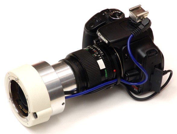 Shown at left is my digital camera upgrade for the Canon CR6-45NM retinal camera.
I build this adapter starting with the original bayonet receptacle from the Polaroid camera which was used
on this instrument. To this I add (1) a mechanical adapter, (2) an electronic interface with
cables to the digital camera shutter and flash sync, (3) a stock Canon lens, and (4) a neutral density filter
to reduce the flash intensity for the digital exposure.
The assembly is shown here with a Canon Digital Rebel XTi SLR camera body and Canon 28mm lens.
The adapter is compatible with all Canon digital SLR models.
Shown at left is my digital camera upgrade for the Canon CR6-45NM retinal camera.
I build this adapter starting with the original bayonet receptacle from the Polaroid camera which was used
on this instrument. To this I add (1) a mechanical adapter, (2) an electronic interface with
cables to the digital camera shutter and flash sync, (3) a stock Canon lens, and (4) a neutral density filter
to reduce the flash intensity for the digital exposure.
The assembly is shown here with a Canon Digital Rebel XTi SLR camera body and Canon 28mm lens.
The adapter is compatible with all Canon digital SLR models.
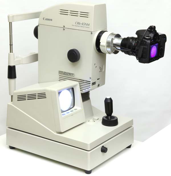 The adapter and digital camera are shown here mounted on the Canon CR6-45NM retinal camera.
The process of taking a non-mydriatic retinal photo is identical to the 35mm film or Polaroid photography originally employed on this unit.
The adapter and digital camera are shown here mounted on the Canon CR6-45NM retinal camera.
The process of taking a non-mydriatic retinal photo is identical to the 35mm film or Polaroid photography originally employed on this unit.
See the installation and operating instructions for more diagrams, photos and details.
See the Canon CR-DA1 operation manual for details of a digital camera adapter Canon made for
the Canon CR6-45NM.
Canon CR4-45NM Non-Mydriatic Retinal Camera
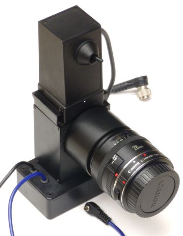 This is a digital camera upgrade for the Canon CR4-45NM retinal camera.
This Canon model is older than the Canon CR6-45NM above, but performs very well and is an excellent
base for a digitally upgraded system.
See the installation and operating instructions for more diagrams, photos and details.
This is a digital camera upgrade for the Canon CR4-45NM retinal camera.
This Canon model is older than the Canon CR6-45NM above, but performs very well and is an excellent
base for a digitally upgraded system.
See the installation and operating instructions for more diagrams, photos and details.
Canon CF-60U and CF-60ZA Retinal Cameras
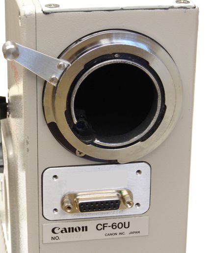 The Canon CF-60U retinal camera originally used the Canon F-A 35mm film camera body, which was a special model of the
popular Canon F 35mm film camera. Upgrading this instrument to digital requires that the old "pogo pin" connector to the film camera
be removed and replaced with a standard connector and electronic interface circuit which connects the instrument joystick and flash synchronization
to the digital camera. Shown here is the rear port area with this connector upgrade installed.
Installing this upgraded connector involves disassembling the upper unit, and then cutting and soldering
the internal wiring. This in turn requires either sending the upper unit to me,
or using the services of an on-site electronics technician following my documented instructions.
The Canon CF-60U retinal camera originally used the Canon F-A 35mm film camera body, which was a special model of the
popular Canon F 35mm film camera. Upgrading this instrument to digital requires that the old "pogo pin" connector to the film camera
be removed and replaced with a standard connector and electronic interface circuit which connects the instrument joystick and flash synchronization
to the digital camera. Shown here is the rear port area with this connector upgrade installed.
Installing this upgraded connector involves disassembling the upper unit, and then cutting and soldering
the internal wiring. This in turn requires either sending the upper unit to me,
or using the services of an on-site electronics technician following my documented instructions.
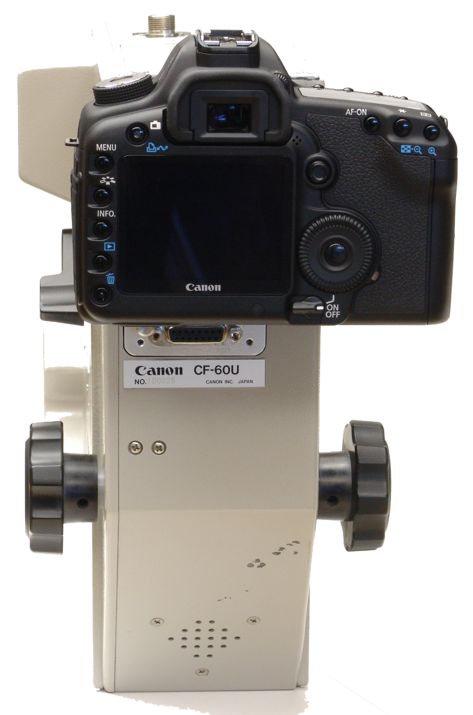 After the electronic connector is installed, a full-frame Canon 5D Mark II digital SLR is mechanically adapted to the rear port
bayonet fitting of the instrument. A digital camera attached via an ordinary adapter ring is not parfocal with the original film camera operation,
the focal plane of the digital camera being several mm further back than the film camera's. Thus a modified bayonet attachment assembly
(not shown) replaces the original on the back of the instrument, to allow parfocal attachment of the digital camera.
Not shown here is the electronic interface cable (see next photo).
After the electronic connector is installed, a full-frame Canon 5D Mark II digital SLR is mechanically adapted to the rear port
bayonet fitting of the instrument. A digital camera attached via an ordinary adapter ring is not parfocal with the original film camera operation,
the focal plane of the digital camera being several mm further back than the film camera's. Thus a modified bayonet attachment assembly
(not shown) replaces the original on the back of the instrument, to allow parfocal attachment of the digital camera.
Not shown here is the electronic interface cable (see next photo).
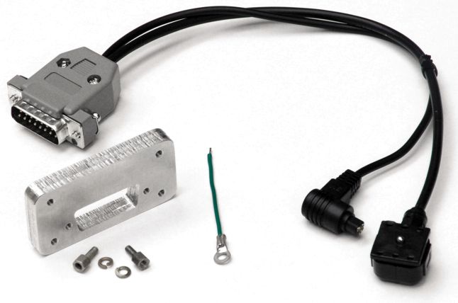 These are the individual components for the electronic interface to digitally upgrade the Canon CF-60U retinal camera.
The bracket is a custom-machined piece to replace the original "pogo pin" assembly that connected the instrument
to the old film camera. The connector receptacle (not shown, see above photos) mounts in the large hole in the bracket, and connects
to the mating plug on the cable. .
The cable connects the digital camera,
splitting into two connectors, one for the Canon shutter remote and another for the Canon hot-shoe flash synchronization.
An electronic interface circuit contained inside the grey connector hood converts the logic and levels of the film camera signals
to be compatible with the digital connections.
These are the individual components for the electronic interface to digitally upgrade the Canon CF-60U retinal camera.
The bracket is a custom-machined piece to replace the original "pogo pin" assembly that connected the instrument
to the old film camera. The connector receptacle (not shown, see above photos) mounts in the large hole in the bracket, and connects
to the mating plug on the cable. .
The cable connects the digital camera,
splitting into two connectors, one for the Canon shutter remote and another for the Canon hot-shoe flash synchronization.
An electronic interface circuit contained inside the grey connector hood converts the logic and levels of the film camera signals
to be compatible with the digital connections.
Olympus ENF Type P3 Endoscope to Canon SD750 Camera
About the application:
A modern medical endoscope is an instrument to illuminate and examine deep within a narrow channel
through a thin fiber optic imaging bundle. Typically this image is presented to the examiner through
an eyepiece with a very narrow field of view. The examiner may view the image directly by looking
into the eyepiece, or on an attached display, typically made to the eyepiece through a C-mount relay lens
adapter to a video camera. Attachment to current digital cameras is feasible but not supported by the
medical endoscope manufacturers. This project sought to attach a digital camera to an Olympus ENF Type P3
endoscope to provide both a live digital video display and recording for teaching,
and high-resolution still digital photography.
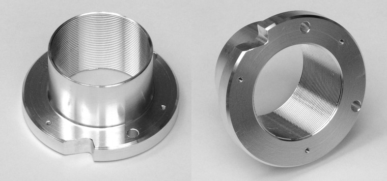 Why adapt an un-adaptable camera?
Important to the endoscope user is the light weight of the instrument and attachments, which must be held and
manipulated in one hand during an examination. This suggests the use of the
high-quality but ultra-compact digital cameras such as the Canon SD series (Canon SD750, Canon SD790). It is a frustratingly
universal lack of compact digital cameras of all makes that they provide no means to attach lens accessories, and are therefore not mechanically
adaptable to instrumentation, although they are quite suitable optically. For this reason I developed a flanged-threaded
adapter tube, shown in this photo, for securely attaching accessories to the Canon SD cameras.
This tube provides a 30mm (M30x0.75) internal thread for attaching accessories, while allowing
for the free movement and extension of the camera lens turret.
Why adapt an un-adaptable camera?
Important to the endoscope user is the light weight of the instrument and attachments, which must be held and
manipulated in one hand during an examination. This suggests the use of the
high-quality but ultra-compact digital cameras such as the Canon SD series (Canon SD750, Canon SD790). It is a frustratingly
universal lack of compact digital cameras of all makes that they provide no means to attach lens accessories, and are therefore not mechanically
adaptable to instrumentation, although they are quite suitable optically. For this reason I developed a flanged-threaded
adapter tube, shown in this photo, for securely attaching accessories to the Canon SD cameras.
This tube provides a 30mm (M30x0.75) internal thread for attaching accessories, while allowing
for the free movement and extension of the camera lens turret.
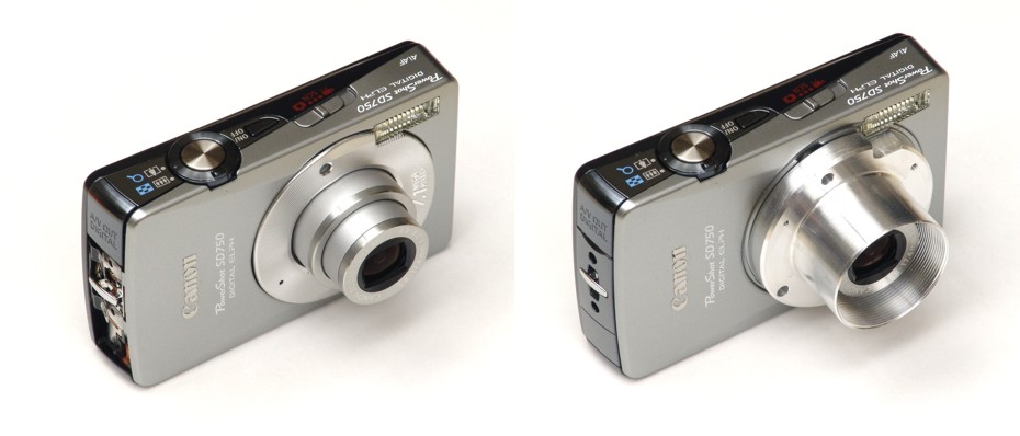 The adapter tube for Canon SD cameras:
The adapter tube attaches permanently to the camera body as shown in the two views of this photo.
On the left is the original camera with the lens turret extended. On the right is the camera
as modified by the attachment of the adapter.
This requires disassembling and separating the front metal cover from the camera,
gently removing the decorative bezel (held on by contact adhesive) from around the camera lens passage of the cover,
drilling three precisely placed miniature holes around the lens passage in the cover,
attaching the adapter to the cover with three miniature screws, and reassembling the
camera.
This modification is thus not a user-installable item, requiring modification at the machine shop here, with
careful technique to avoid damaging the fragile internal camera mechanisms.
The adapter piece is machined from aluminum to be very lightweight yet strong.
It will fit many of the SD models, namely all the Canon SD7xx series which use this case design.
The success of this adaptation depends on (1) the easy disassembly of the front cover, (2) the cover being
made of sturdy metal and not plastic, and (3) there being some clearance behind the cover at the critical
points where the newly added screw heads project back. The design would work on other
Canon compact models, or other brands of compact cameras, which have these cover characteristics.
The adapter tube for Canon SD cameras:
The adapter tube attaches permanently to the camera body as shown in the two views of this photo.
On the left is the original camera with the lens turret extended. On the right is the camera
as modified by the attachment of the adapter.
This requires disassembling and separating the front metal cover from the camera,
gently removing the decorative bezel (held on by contact adhesive) from around the camera lens passage of the cover,
drilling three precisely placed miniature holes around the lens passage in the cover,
attaching the adapter to the cover with three miniature screws, and reassembling the
camera.
This modification is thus not a user-installable item, requiring modification at the machine shop here, with
careful technique to avoid damaging the fragile internal camera mechanisms.
The adapter piece is machined from aluminum to be very lightweight yet strong.
It will fit many of the SD models, namely all the Canon SD7xx series which use this case design.
The success of this adaptation depends on (1) the easy disassembly of the front cover, (2) the cover being
made of sturdy metal and not plastic, and (3) there being some clearance behind the cover at the critical
points where the newly added screw heads project back. The design would work on other
Canon compact models, or other brands of compact cameras, which have these cover characteristics.
Reversible, non-interfering design:
The notch in the flange of the adapter provides clearance to the built-in camera flash,
which otherwise would be partly obscured. Two additional holes in the flange provide passages through the
adapter for features on the front of the camera, namely the focus-assist lamp and the microphone.
While the endoscope does not use these camera features,
the adapter is designed to not interfere with the normal operation of the camera when off the endoscope.
The only difference from normal operation
is that normally the lens turret retracts when the power is off, making the camera more compact,
while on the modified camera the adapter is always projecting.
The modification may be reversed by disassembling the cover again and removing the miniature screws holding on
the adapter. Replacing the decorative bezel then hides the holes added to the front cover.
Optical compatibility:
The Canon SD series cameras, and indeed just about all compact cameras, have a lens and iris smaller in scale than the
human eye, which means that they will couple directly to just about any eyepiece or other instrument designed
for eye viewing. The modification to accept attachments thus converts the camera into something
very versatile for instrumentation applications. One could only wish that the original camera came with an attachment
provision. Advancing technology and economy have made these cameras cost less than this custom modification work.
Endoscope eyepiece optics: A consideration with fiber endoscopes is the narrow presentation in the eyepiece view.
The apparent size of the circular field of view in an endoscope eyepiece is typically
only 7 degrees, versus about 40 or 45 degrees in a typical wide-field microscope eyepiece.
Indeed, when first using an endoscope, the observer tends to feel as though the instrument is not properly designed, since
the image is so small compared to what one is used to in other optical instruments such as a compound microscope.
But the narrow view and low magnification is in fact a sound design.
Since the fiber bundle represents only a few hundred pixels across, comparable to the resolution of the observer's eye
over a similar angle, magnifying the image further would not improve the visual resolution.
Since minimal lighting is desirable in endoscopy to minimize heating of tissues,
and image brightness is increased by lower eyepiece magnification, the eyepiece design is chosen for the minimal
magnification that will just allow an acute eye to resolve the individual fibers or a little better.
While this is all suitable for visual use, the attachment of a camera presents a challenge, lest the useful image crop to the narrow
center of the camera field of view, leaving most of the field unused.
When attaching an afocal camera with a simple mechanical adapter, the camera must be capable of an almost telescopic
zoom to enlarge a 7 degree subject enough to fill the camera field of view, equivalent to a 200mm lens on a 35mm film camera.
Otherwise the endoscope image will never be larger than a small circle in a larger black camera field.
A typical point-and-shoot camera might have an optical zoom range of
4:1, with the lens being equivalent to a 28mm to 112mm zoom lens in a 35mm film camera,
corresponding to an angle of view from 45 degrees (wide angle)
to 12 degrees (telephoto) in the vertical aspect.
Such a camera at maximum telephoto zoom will not fill the photograph's vertical aspect with optical zoom only,
requiring that a small extra digital zoom be applied.
Since the camera's megapixels of resolution far out-resolve the kilopixels of effective endoscope fiber resolution,
the slight application of digital zoom does not limit the resolution of the overall system.
At the same time, applying maximum telephoto zoom in the camera lens will retract the camera's entrance pupil maximally
away from the front vertex of the lens assembly, so the exit pupil of the endoscope eyepiece must still be able to reach the entrance pupil
within the constraints imposed by the mechanical coupling.
But happily, all these optical and mechanical issues resolve into a good fit with the Canon SD series and Nikon L series of compact cameras.
Endoscope eyepieces tend to have an extra generous eye relief, by virtue of the fact that the fiber bundle, which is the aperture stop of
the system, is very close to the eyepiece lens.
The exit pupil, being the image of this aperture stop as imaged by the eyepiece, can thus be 25mm or more above the end of the eyepiece,
so the reach into a compact telephoto lens is typically feasible.
Contrast this with a compound microscope which, although having a similar eyepiece, has
an aperture stop imposed by the microscope objective which is 160mm or more from the eyepiece, placing the exit pupil only about 16mm above
the end of the eyepiece, and not able to reach the entrance pupil of a zoomed camera lens.
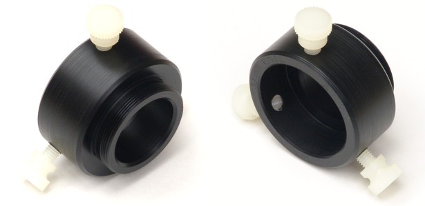 The endoscope adapter:
A second custom adapter piece attaches the modified Canon SD750 camera to the endoscope's
standard mushroom eyepiece, also known as the endoscope "B-cup" eyepiece.
A 30mm thread attaches to the threads of the modified Canon SD750,
and a bushing with three Nylon thumbscrews attaches to the endoscope.
This piece is machined from polyacetal engineering polymer (Delrin).
A larger thread size or a step-down ring would make this adapter compatible with
other cameras with filter threads already on the lens, or that accept conversion lens adapter tubes
with filter threads.
More complex (but more convenient) clamping systems are typically used on older stock adapters for these instruments,
but these are not feasible to produce in a custom shop.
The endoscope adapter:
A second custom adapter piece attaches the modified Canon SD750 camera to the endoscope's
standard mushroom eyepiece, also known as the endoscope "B-cup" eyepiece.
A 30mm thread attaches to the threads of the modified Canon SD750,
and a bushing with three Nylon thumbscrews attaches to the endoscope.
This piece is machined from polyacetal engineering polymer (Delrin).
A larger thread size or a step-down ring would make this adapter compatible with
other cameras with filter threads already on the lens, or that accept conversion lens adapter tubes
with filter threads.
More complex (but more convenient) clamping systems are typically used on older stock adapters for these instruments,
but these are not feasible to produce in a custom shop.
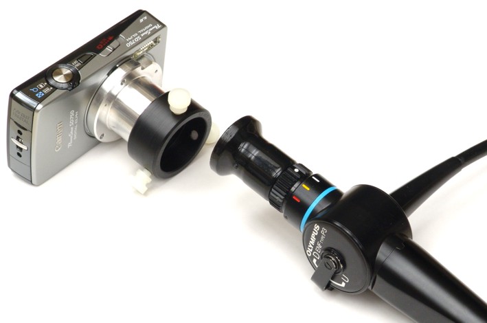 The assembly:
This photo shows the arrangement of the Olympus endoscope to the modified Canon camera and custom adapter.
The endoscope provides a standard mushroom-shaped end ("B-cup") to the eyepiece.
This shape allows for direct viewing by eye, or for the mechanical attachment of accessories.
The assembly:
This photo shows the arrangement of the Olympus endoscope to the modified Canon camera and custom adapter.
The endoscope provides a standard mushroom-shaped end ("B-cup") to the eyepiece.
This shape allows for direct viewing by eye, or for the mechanical attachment of accessories.
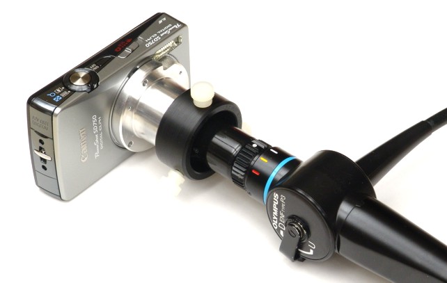 Here we see the completed assembly.
The thumbscrews allow for rapid attachment, rotational alignment, and detachment of the adapted camera.
The attachment is firm and definite, yet the Nylon thumbscrew tips will not mar the hard eyepiece body.
Endoscope eyepieces typically provide a very narrow field of view, so setting about a 5X telephoto zoom on the Canon SD750
fills the camera field of view with the endoscopic view in an inscribed crop. By using the camera
zoom, we eliminate the need for any costly beam-expanding optics in the adapter. The potential Moire effect due to the digital pixels sampling
the discrete fibers of the image is nulled out by adjusting the rotation of the camera on the endoscope,
and by the high resolution of the camera oversampling the fiber ends.
The nearly telecentric exit pupil of the endoscope eyepiece makes this type of adaptation possible with
virtually any camera lens with sufficient zoom. The fiber optics of the endoscope are limited to some hundreds of elements
in each dimension, equivalent to about 1 megapixel of image sampling,
so the digital camera's many megapixels of resolution are more than adequate for a full rendition
of the instrument's capabilities.
Here we see the completed assembly.
The thumbscrews allow for rapid attachment, rotational alignment, and detachment of the adapted camera.
The attachment is firm and definite, yet the Nylon thumbscrew tips will not mar the hard eyepiece body.
Endoscope eyepieces typically provide a very narrow field of view, so setting about a 5X telephoto zoom on the Canon SD750
fills the camera field of view with the endoscopic view in an inscribed crop. By using the camera
zoom, we eliminate the need for any costly beam-expanding optics in the adapter. The potential Moire effect due to the digital pixels sampling
the discrete fibers of the image is nulled out by adjusting the rotation of the camera on the endoscope,
and by the high resolution of the camera oversampling the fiber ends.
The nearly telecentric exit pupil of the endoscope eyepiece makes this type of adaptation possible with
virtually any camera lens with sufficient zoom. The fiber optics of the endoscope are limited to some hundreds of elements
in each dimension, equivalent to about 1 megapixel of image sampling,
so the digital camera's many megapixels of resolution are more than adequate for a full rendition
of the instrument's capabilities.
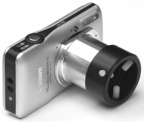 This is the endoscope adapter updated for the more recent Canon SD1300 compact camera.
Canon changes camera models frequently, requiring frequent adjustments to the adapter designs.
This is the endoscope adapter updated for the more recent Canon SD1300 compact camera.
Canon changes camera models frequently, requiring frequent adjustments to the adapter designs.
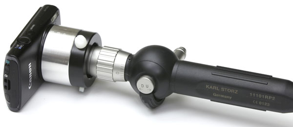 This is the endoscope adapter updated for the more recent Canon ELPH 310HS compact camera, shown with
a Storz 11101RP2 endoscope. This Storz model provides a standard B-cup eyepiece like the Olympus P3 endoscope above.
This Canon camera provides a digital teleconverter and 8X optical zoom which allows coupling to the difficult
field of view requirements and eye relief of the endoscope, without additional optics.
This adaptation requires I sell the new camera itself (see ordering page), modified with the adapter installed, since the only feasible attachment
method requires the delicate disassembly and modification of the original shell of the camera.
This is the endoscope adapter updated for the more recent Canon ELPH 310HS compact camera, shown with
a Storz 11101RP2 endoscope. This Storz model provides a standard B-cup eyepiece like the Olympus P3 endoscope above.
This Canon camera provides a digital teleconverter and 8X optical zoom which allows coupling to the difficult
field of view requirements and eye relief of the endoscope, without additional optics.
This adaptation requires I sell the new camera itself (see ordering page), modified with the adapter installed, since the only feasible attachment
method requires the delicate disassembly and modification of the original shell of the camera.
Digital SLR Camera Adapter for Zeiss OPMI instruments (slit lamps and operating microscopes) with Zeiss beamsplitter
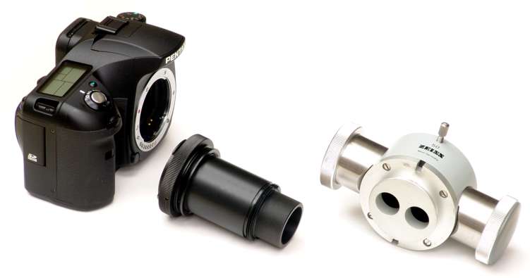 The adapter shown in the photo adapts a digital SLR camera on the left to a Zeiss OPMI beamsplitter on the right,
The Zeiss OPMI (operating microscope) system is an infinity-optics design (sometimes called "parallel optics", which is not
quite proper) which allows for the insertion of the beamsplitter shown into the stacked instrument components using a
dovetail and dovetail-receptacle mechanism.
This same OPMI dovetail interface is used on Zeiss operating microscopes as well as Zeiss slit lamps, and the digital
camera adapter is compatible with any Zeiss OPMI instrument accessory fitting (see the drawing
with details of this fitting).
The custom adapter allows the use of any digital SLR camera via a T-mount mechanical interface,
for which a Pentax K10D digital SLR is shown here.
The adapter shown in the photo adapts a digital SLR camera on the left to a Zeiss OPMI beamsplitter on the right,
The Zeiss OPMI (operating microscope) system is an infinity-optics design (sometimes called "parallel optics", which is not
quite proper) which allows for the insertion of the beamsplitter shown into the stacked instrument components using a
dovetail and dovetail-receptacle mechanism.
This same OPMI dovetail interface is used on Zeiss operating microscopes as well as Zeiss slit lamps, and the digital
camera adapter is compatible with any Zeiss OPMI instrument accessory fitting (see the drawing
with details of this fitting).
The custom adapter allows the use of any digital SLR camera via a T-mount mechanical interface,
for which a Pentax K10D digital SLR is shown here.
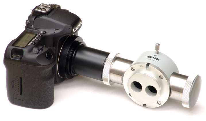 Here is the adapter and beamsplitter assembled with a Canon 40D digital SLR camera.
A screw-and-lockring feature on the adapter allows for parfocal calibration of the camera to the binocular eyepiece view of the Zeiss instrument.
Parfocal calibration permits shooting precisely focused digital pictures using the normal instrument view, instead of
having to focus through the camera viewfinder.
Here is the adapter and beamsplitter assembled with a Canon 40D digital SLR camera.
A screw-and-lockring feature on the adapter allows for parfocal calibration of the camera to the binocular eyepiece view of the Zeiss instrument.
Parfocal calibration permits shooting precisely focused digital pictures using the normal instrument view, instead of
having to focus through the camera viewfinder.
Optically, this is an afocal-focal adapter design, which incorporates a multielement lens to focalize the infinity image
at the proper position and scale for the digital camera sensor, taking into account the Zeiss instrument's aperture stops and
mechanical constraints. The Zeiss attachment mechanism at the beamsplitter is an unusual threaded locking-tab type.
Photographic lighting using the normal slit illuminator is sufficient if the digital camera is set to a high ISO sensitivity.
Thus the full range of slit lamp diagnostic examination may be photographed.
Another convenient feature of this adaptation is that the built-in flash of the digital camera can be raised, and diffused and reflected
with a white card, to take low-magnification, high-resolution photos of the entire eye.
The grub-screw feature of the T-mount adapter provides rotational alignment of the camera in any desired orientation.
The Zeiss OPMI beamsplitter provides two ports, one for each of the two stereoscopic binocular views, and the adapted camera may
be mounted on either side. Two digital cameras and adapters, one on each side of a single beamsplitter, would provide stereoscopic pair photography!
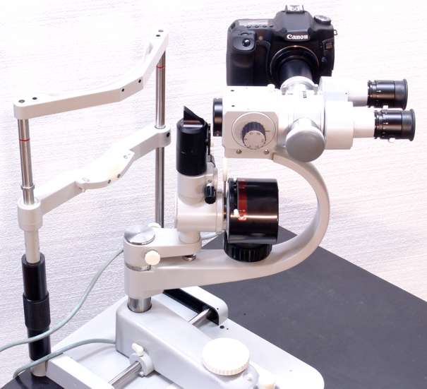 Here is the adapted camera and beamsplitter assembled with a Zeiss slit lamp.
The adapter and camera are lightweight and do not interfere with the smooth motion and stability of the microscopic examination.
Part of this economy is to omit a 90-degree mirror from the adapter, which results in mirrored photographs, which are then
unmirrored later in software.
A separate adapter cable (not shown) connects the digital camera remote shutter to the Zeiss slit lamp joystick button,
allowing the examiner to use one hand to manipulate the instrument into position and focus, and shoot digital photos,
while leaving the other hand free to assist the patient. We've also made footswitch shutter releases for practitioners
favoring a "third hand" option.
Here is the adapted camera and beamsplitter assembled with a Zeiss slit lamp.
The adapter and camera are lightweight and do not interfere with the smooth motion and stability of the microscopic examination.
Part of this economy is to omit a 90-degree mirror from the adapter, which results in mirrored photographs, which are then
unmirrored later in software.
A separate adapter cable (not shown) connects the digital camera remote shutter to the Zeiss slit lamp joystick button,
allowing the examiner to use one hand to manipulate the instrument into position and focus, and shoot digital photos,
while leaving the other hand free to assist the patient. We've also made footswitch shutter releases for practitioners
favoring a "third hand" option.
See also a high-resolution (3872 x 2592) digital anterior
photograph [513KB JPEG file] as taken with this instrument and
adapter.
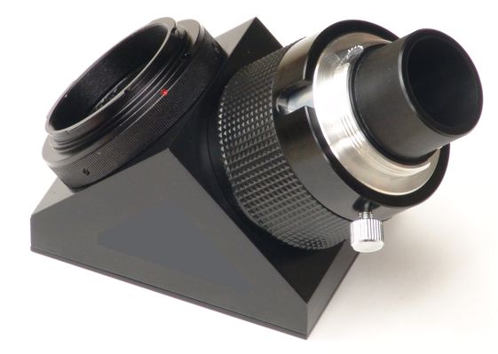 The larger design at the left adds a precision diagonal mirror fitting via an "elbow" component to the Zeiss OPMI adapter.
Unlike the simpler straight-tube design above, this produces unmirrored images in the digital camera.
The T-mount exit fitting adapts easily to Canon, Nikon, or other digital SLR cameras.
A telescoping mechanism with thumbscrew lock provides both parfocal calibration to the instrument
and various orientations to suit the desired clearance around the instrument.
Compare my design to an original Zeiss f=137 video camera adapter (manufactured for Zeiss by Urban Engineering in the US) from many
years ago and no longer available, seen in this
photo 1
and
photo 2.
The larger design at the left adds a precision diagonal mirror fitting via an "elbow" component to the Zeiss OPMI adapter.
Unlike the simpler straight-tube design above, this produces unmirrored images in the digital camera.
The T-mount exit fitting adapts easily to Canon, Nikon, or other digital SLR cameras.
A telescoping mechanism with thumbscrew lock provides both parfocal calibration to the instrument
and various orientations to suit the desired clearance around the instrument.
Compare my design to an original Zeiss f=137 video camera adapter (manufactured for Zeiss by Urban Engineering in the US) from many
years ago and no longer available, seen in this
photo 1
and
photo 2.
The Zeiss item provided a manually adjustable iris to set the optical aperture from f/8 to f/44,
which trades off the light available for exposure with the depth of field in focus.
In my DSLR adapter this aperture feature is available by assembling an optional,
non-adjustable aperture-stop disk which I fabricate for any desired f/number next to the lens.
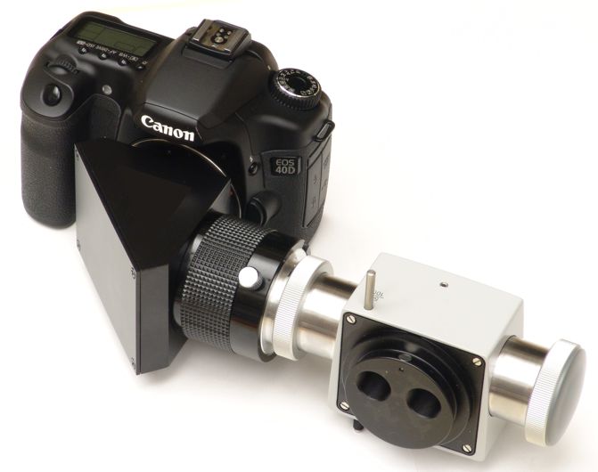 Here is the elbow adapter shown with a Zeiss beamsplitter as used with Zeiss SL-120 and SL-130 slit lamps.
These Zeiss models use a slightly modified dovetail instrument interface that is not quite compatible with the
classic Zeiss OPMI instruments, but the beamsplitter still provides the same OPMI accessory interface on the
exit attachment point.
The digital SLR shown here is a Canon 40D; all Canon SLR models are compatible.
Here is the elbow adapter shown with a Zeiss beamsplitter as used with Zeiss SL-120 and SL-130 slit lamps.
These Zeiss models use a slightly modified dovetail instrument interface that is not quite compatible with the
classic Zeiss OPMI instruments, but the beamsplitter still provides the same OPMI accessory interface on the
exit attachment point.
The digital SLR shown here is a Canon 40D; all Canon SLR models are compatible.
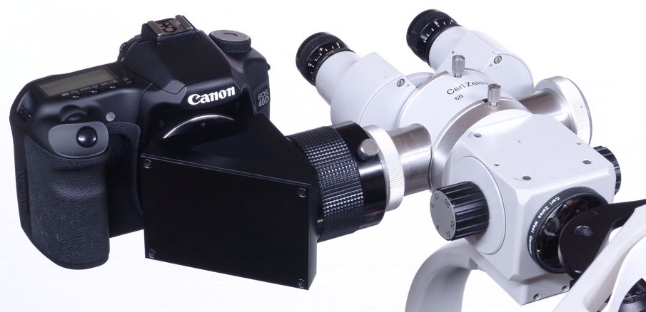 Here is the elbow adapter, Zeiss OPMI beamsplitter, and digital SLR shown on a Zeiss 125/16 slit lamp.
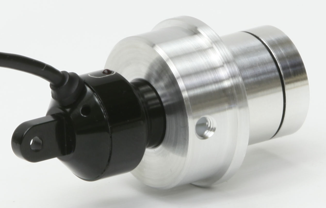 This is my adapter for a Global (brand) operating (surgical or dental) microscope, with attaches a
LoupeCam miniature HD camera to the microscope beamsplitter. Global surgical microscopes are similar in optical principle to the Zeiss OPMI instruments,
but with slightly different (and incompatible) mechanical fittings, such that attachments and adapters for one will not work with the other.
The assembly is very small; the diameter of the camera body shown is a little less than an inch in diameter.
This camera provides a USB connection for live HD video and high-resolution still photography.
See additional photos from the Global-LoupeCam adapter here.
This is my adapter for a Global (brand) operating (surgical or dental) microscope, with attaches a
LoupeCam miniature HD camera to the microscope beamsplitter. Global surgical microscopes are similar in optical principle to the Zeiss OPMI instruments,
but with slightly different (and incompatible) mechanical fittings, such that attachments and adapters for one will not work with the other.
The assembly is very small; the diameter of the camera body shown is a little less than an inch in diameter.
This camera provides a USB connection for live HD video and high-resolution still photography.
See additional photos from the Global-LoupeCam adapter here.
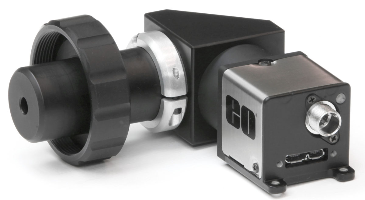 This is another adapter for the Global operating microscope, which is a modification of an existing Global adapter
which originally used a now-obsolete Panasonic GP-KS162HD "lipstick" camera.
I retrofitted the original Global adapter to provide a standard C-mount camera fitting, and shortened the length to match the focal plane to the C-mount optical requirements.
Thus the adapter can now work with any standard industrial/scientific camera rather than depending on one make-and-model like the original design.
This result is shown here with an Edmund Optics EO-1312C HD color camera, which provides a USB 3.0 connection to a computer
for high-resolution stills and HD live video.
The cost for this modification work is only a fifth of the price of a new adapter with similar capabilities.
See the detailed instructions for installing this adapter.
This is another adapter for the Global operating microscope, which is a modification of an existing Global adapter
which originally used a now-obsolete Panasonic GP-KS162HD "lipstick" camera.
I retrofitted the original Global adapter to provide a standard C-mount camera fitting, and shortened the length to match the focal plane to the C-mount optical requirements.
Thus the adapter can now work with any standard industrial/scientific camera rather than depending on one make-and-model like the original design.
This result is shown here with an Edmund Optics EO-1312C HD color camera, which provides a USB 3.0 connection to a computer
for high-resolution stills and HD live video.
The cost for this modification work is only a fifth of the price of a new adapter with similar capabilities.
See the detailed instructions for installing this adapter.
These Zeiss operating microscope digital camera attachments
can be used on classic Leica instruments such as the Leica 690 operating microscopes
via an Zeiss-Leica adapter. See the drawing (1-page PDF file).
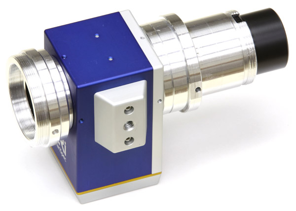 This attachment provides live imaging of microscopic surgical
fields with tunable color filtering.
This assembly combines my Zeiss OPMI adapter with custom fittings to a CRi Varispec
LCTF (liquid crystal tunable filter, model VIS-07-HC-20, which is the blue box), ending
in another custom adapter to an Apogee high-sensitivity camera with D02 (2"-24) thread mount.
An alternate back end provides compatibility with C-mount cameras.
The camera adapter assembly consists (1) a custom fitting with
f=125mm f/5.2 objective lens for the Zeiss OPMI accessory port, (2)
a Thorlabs CRM1/M cage rotation mount with polarizer element,
(3) a custom adapter from the previous components to the Varispec LCTF
dovetail fitting, (4) a custom adapter from the LCTF dovetail to Apogee
camera 2"-24 thread, providing a focusing adjustment. A second version
of (4) consists of a custom adapter from the LCTF dovetail to a C-mount
camera, incorporating an second lens (f=50mm) to reduce the combined
effective focal length to f=75mm f/3.1 for cropping to a smaller format.
A third version of (4) consists of an eyepiece adapter for direct visual
observation. The focal lengths and apertures of the optical system are
chosen to yield a field of view in the cameras which covers approximately
the same field of view as in the surgeon's eyepieces.
See the CAD model exploded assembly diagram here [1-page PDF file].
This attachment provides live imaging of microscopic surgical
fields with tunable color filtering.
This assembly combines my Zeiss OPMI adapter with custom fittings to a CRi Varispec
LCTF (liquid crystal tunable filter, model VIS-07-HC-20, which is the blue box), ending
in another custom adapter to an Apogee high-sensitivity camera with D02 (2"-24) thread mount.
An alternate back end provides compatibility with C-mount cameras.
The camera adapter assembly consists (1) a custom fitting with
f=125mm f/5.2 objective lens for the Zeiss OPMI accessory port, (2)
a Thorlabs CRM1/M cage rotation mount with polarizer element,
(3) a custom adapter from the previous components to the Varispec LCTF
dovetail fitting, (4) a custom adapter from the LCTF dovetail to Apogee
camera 2"-24 thread, providing a focusing adjustment. A second version
of (4) consists of a custom adapter from the LCTF dovetail to a C-mount
camera, incorporating an second lens (f=50mm) to reduce the combined
effective focal length to f=75mm f/3.1 for cropping to a smaller format.
A third version of (4) consists of an eyepiece adapter for direct visual
observation. The focal lengths and apertures of the optical system are
chosen to yield a field of view in the cameras which covers approximately
the same field of view as in the surgeon's eyepieces.
See the CAD model exploded assembly diagram here [1-page PDF file].
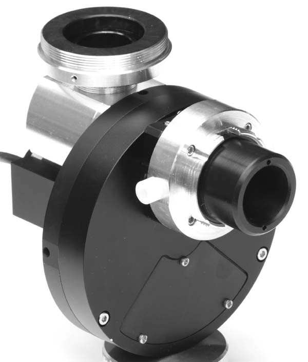 This is a similar assembly to the LCTF attachment above, but uses a
Thorlabs FW103S/M motorized filter wheel for filter switching instead of a costly tunable filter.
The filter wheel (large black round item) is computer controlled by a stepper motor (left) for rapid switching (55 milliseconds/switch).
The front end (right) fits Zeiss OPMI surgical microscopes, including an f=125mm objective lens and Thorlabs CRM1/M cage rotation mount with polarizer element,
and the back end (top) provides a diagonal mirror and Apogee camera 2"-24 thread mount.
See the CAD model exploded assembly diagram here [1-page PDF file].
This is a similar assembly to the LCTF attachment above, but uses a
Thorlabs FW103S/M motorized filter wheel for filter switching instead of a costly tunable filter.
The filter wheel (large black round item) is computer controlled by a stepper motor (left) for rapid switching (55 milliseconds/switch).
The front end (right) fits Zeiss OPMI surgical microscopes, including an f=125mm objective lens and Thorlabs CRM1/M cage rotation mount with polarizer element,
and the back end (top) provides a diagonal mirror and Apogee camera 2"-24 thread mount.
See the CAD model exploded assembly diagram here [1-page PDF file].
Another example of polarization microscopy work is my
copying of a rare Leica polarization filter holder [2-page PDF file].
This is a filter slider that slightly tilts the filter elements to avoid surface reflections.
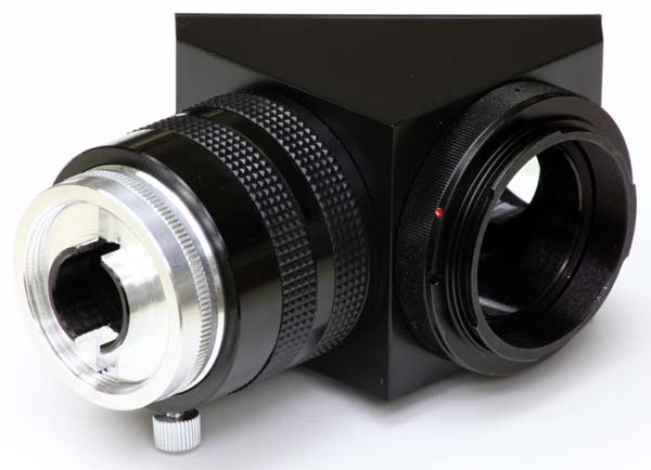 The diagonal adapter can also be fitted to the Haag-Streit BQ900 slit lamp via the standard beamsplitter port.
The Haag-Streit coupling is similar to, but incompatible with, the Zeiss type.
The diagonal adapter can also be fitted to the Haag-Streit BQ900 slit lamp via the standard beamsplitter port.
The Haag-Streit coupling is similar to, but incompatible with, the Zeiss type.
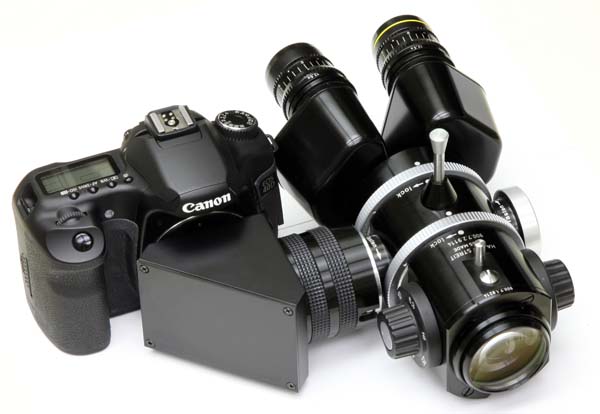 This is the diagonal adapter on a Haag-Streit BQ900 slit lamp, shown assembled with a Canon 40D digital SLR.
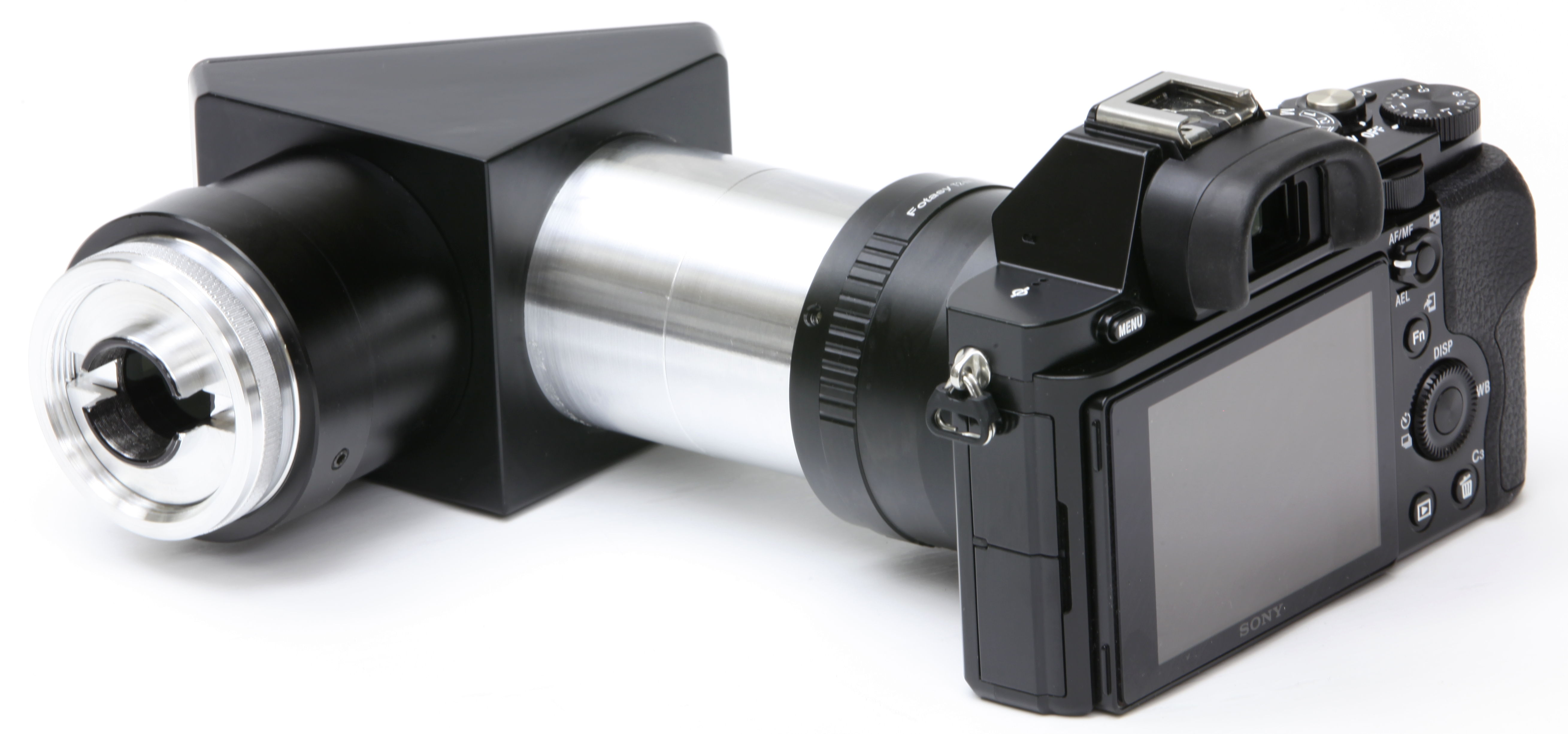 This longer focal-length version of the adapter for the Haag-Streit BQ900 works with full-frame cameras,
shown here with a Sony E-mount bayonet fitting and Sony A7S mirrorless camera.
This is readily configured for Canon or Nikon full-frame DSLRs.
This longer focal-length version of the adapter for the Haag-Streit BQ900 works with full-frame cameras,
shown here with a Sony E-mount bayonet fitting and Sony A7S mirrorless camera.
This is readily configured for Canon or Nikon full-frame DSLRs.
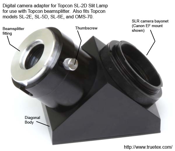 This is the diagonal adapter fitted to the Topcon SL-2D slit lamp via the Topcon beamsplitter.
This also fits the Topcon SL-2E, SL-5D, SL-6E, and the Topcon OMS-70 operating microscope.
Technical details and more photographs are here.
This is the diagonal adapter fitted to the Topcon SL-2D slit lamp via the Topcon beamsplitter.
This also fits the Topcon SL-2E, SL-5D, SL-6E, and the Topcon OMS-70 operating microscope.
Technical details and more photographs are here.
HD Video Camera Adapter for Zeiss OPMI binocular
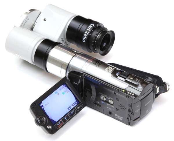 Instead of using the Zeiss OPMI beamsplitter for camera mounting, it is also possible to adapt cameras directly
to the eyetubes of the binocular in place of the eyepieces.
Later models of the Zeiss OPMI binocular provide eyetubes with magnetic clutches to hold the eyepieces
in place, instead of the older sliding friction fit or screw-on attachment. The adapter shown here couples an HD video camera to this
magnetic eyetube mechanism. I produced this adapter to work with small flash-memory HD video cameras such as the Canon HF20,
Canon HF200 (shown in the photo), and Canon HF M300.
Newer HD video camera models also work well as long as they provide a 37mm filter thread (or other standard size thread)
for attachment to the adapter.
The single camera shown here records ordinary HD video and high-resolution still photos,
as well as providing a live 1080p video feed to an HDTV.
See below for a 3D camera-pair version.
Instead of using the Zeiss OPMI beamsplitter for camera mounting, it is also possible to adapt cameras directly
to the eyetubes of the binocular in place of the eyepieces.
Later models of the Zeiss OPMI binocular provide eyetubes with magnetic clutches to hold the eyepieces
in place, instead of the older sliding friction fit or screw-on attachment. The adapter shown here couples an HD video camera to this
magnetic eyetube mechanism. I produced this adapter to work with small flash-memory HD video cameras such as the Canon HF20,
Canon HF200 (shown in the photo), and Canon HF M300.
Newer HD video camera models also work well as long as they provide a 37mm filter thread (or other standard size thread)
for attachment to the adapter.
The single camera shown here records ordinary HD video and high-resolution still photos,
as well as providing a live 1080p video feed to an HDTV.
See below for a 3D camera-pair version.
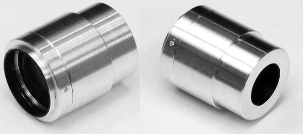 This is a close-up of the HD video camera adapter itself.
The threaded end fits the filter threads of the video camera; the other end precisely fits the Zeiss magnetic eyetube socket.
Optics in the adapter afocalize the Zeiss instrument's image
with a field-of-view angle for an appropriate cropping to the HD video frame width.
More photos for this project are here.
This is a close-up of the HD video camera adapter itself.
The threaded end fits the filter threads of the video camera; the other end precisely fits the Zeiss magnetic eyetube socket.
Optics in the adapter afocalize the Zeiss instrument's image
with a field-of-view angle for an appropriate cropping to the HD video frame width.
More photos for this project are here.
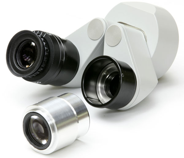 This slighly different custom adapter fits the Zeiss OPMI Visu 200 binocular (f125) instead of the f170 on the Zeiss Lumera binocular.
The receptacle shape of the eyetubes is identical, but the magnetic clutch mechanism differs.
On the eyetube you can see the tiny setscrew we have added to lock the camera adapter into the eyetube
and to lock the rotation of the camera.
This slighly different custom adapter fits the Zeiss OPMI Visu 200 binocular (f125) instead of the f170 on the Zeiss Lumera binocular.
The receptacle shape of the eyetubes is identical, but the magnetic clutch mechanism differs.
On the eyetube you can see the tiny setscrew we have added to lock the camera adapter into the eyetube
and to lock the rotation of the camera.
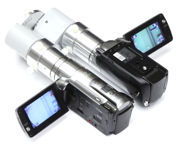 Another project involved generating live 3D video from a Zeiss OPMI Lumera operating microscope
from the binocular eyetubes.
A pair of HDMI video signals from a pair of low-cost HD video cameras mounted on the two Zeiss OPMI eyetubes
feeds into a video processor to produce live 3D HD video on a 3D HDTV.
For the 3D application, each of the two cameras must be rotationally aligned to the other,
so I replaced the original Zeiss magnetic eyetube with a custom thumbscrew type eyetube to provide a locking rotational adjustment.
Another project involved generating live 3D video from a Zeiss OPMI Lumera operating microscope
from the binocular eyetubes.
A pair of HDMI video signals from a pair of low-cost HD video cameras mounted on the two Zeiss OPMI eyetubes
feeds into a video processor to produce live 3D HD video on a 3D HDTV.
For the 3D application, each of the two cameras must be rotationally aligned to the other,
so I replaced the original Zeiss magnetic eyetube with a custom thumbscrew type eyetube to provide a locking rotational adjustment.
Another constraint for the 3D application is that the optical axes of the two Zeiss eyetubes will only separate to about 75mm maximum distance,
which puts the two cameras very close together. While the compact HD cameras are small enough to fit inside this constraint,
the HDMI output connectors are located on the right side of the cameras,
blocking one of the connectors when the cameras are closely mounted side-by-side as shown.
The solution is to invert one of the cameras so that the HDMI connector on each camera is located to the outer side.
The 3D video processor provides the option to invert the images, so the inverted camera image can me returned to upright like its mate.
Inverting one camera also allows both built-in camera displays to fold out like wings as shown.
The 3D processor also provides an X and Y frame shift to cover the remaining degrees of freedom required to align the image pair for
a properly calibrated 3D effect.
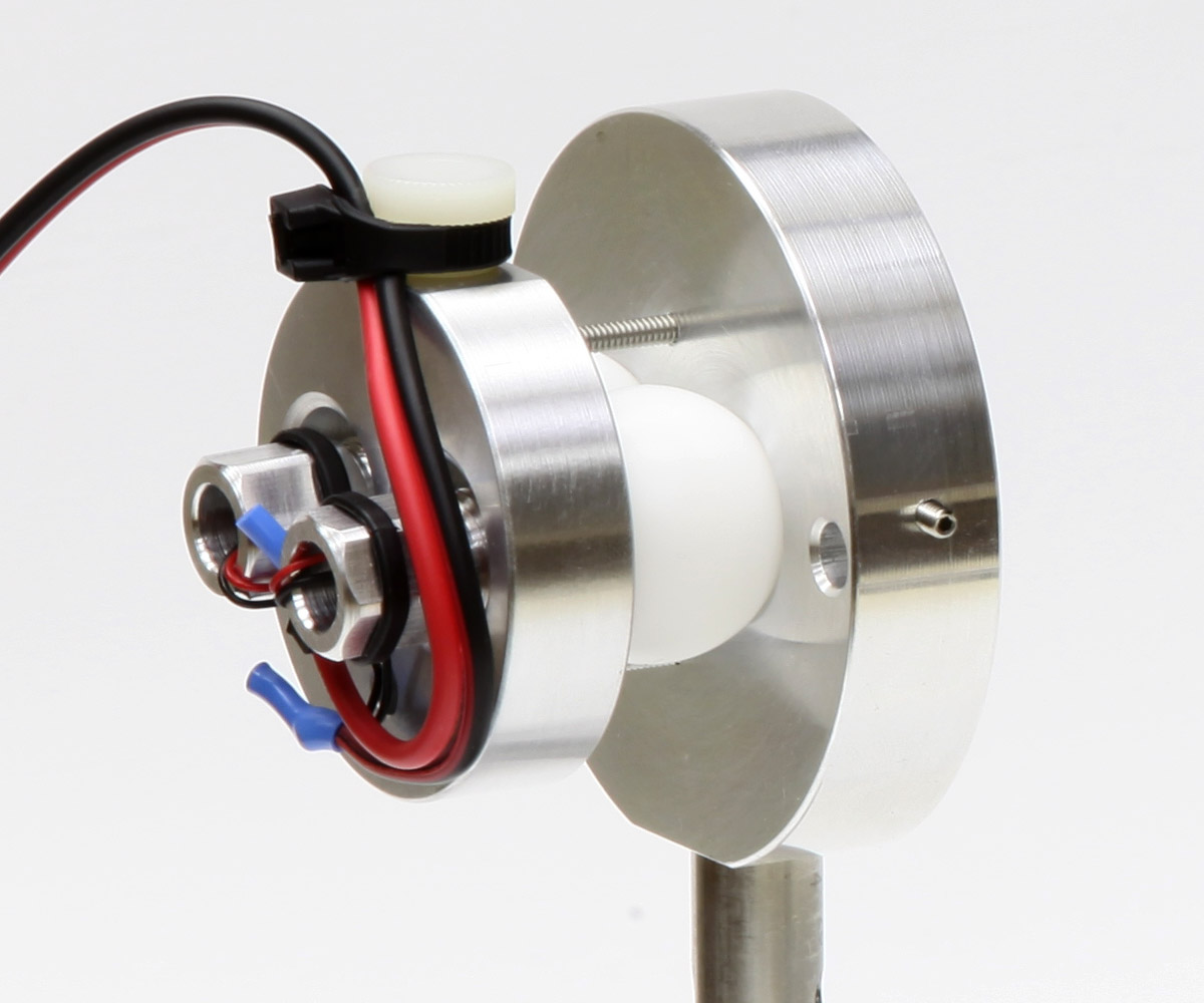 The device at left is my design of a laser collimator used to construct, test, and perfect Zeiss OPMI attachments.
In Zeiss operating microscopes, the two optical paths constituting the left and right pair of stereo views are precisely aligned
in parallel. An adapter to attach a single camera to one side or the other does not have to be too precisely centered, so ordinary machining and mechanical
assembly will provide sufficient alignment.
But in applications where an attachment simultaneously uses both images, such as 3D viewing or photography, the optical axes of the attachment must be more precisely parallel than
ordinary machining tolerances will provide.
If this precise parallelism is not maintained, the two images of the stereo pair will not be centered with respect to each other. Uncentered images produce a binocular view
which the eyes cannot visually converge, or a 3D photograph with displaced centers that cannot be live-viewed.
The principle of the collimator is to produce (1) two laser beams (2) spaced on the OPMI standard
spacing of 22mm alongside the central axis, which beams are also (3) precisely parallel to each other, and (4) precisely normal to the mechanical face of the collimator.
Each beam thus has four degrees of freedom requiring precise control, consisting of a position and angle each for both left/right and up/down directions.
The position is automatically established by the sphere size (conveniently, these are readily available as precision polyacetal bearing balls) and by the precise
machining of the clamping mechanism to hold the spheres.
The angles are precisely adjusted by manually pivoting the spheres within the clamp.
In practice the alignment is done by holding the collimator in a steady fixture, and projecting the laser spots across
a room-sized distance to a vertical wall. To locate the projection of the central axis, a precision mirror is attached to the face of
the collimator, and a third laser beam is reflected from the wall to the collimator and back to the wall.
All these lasers can be inexpensive modules such as are used in laser pointers. Once this projection of the central axis is located and marked,
the target projections of the left and right paths are marked on either side at the standard 22mm separation. A one-time calibration is then performed as follows:
The spherical clamp is loosened, the
spheres holding the lasers are nudged gently by hand until the beam spots fall upon the left and right targets respectively, and the clamp is tightened.
Precise parallelism to 1 minute of arc can be considered a high standard for optical instrumentation.
One minute of arc is about the limit of visual acuity of the human eye,
making it more than sufficient for direct visual instruments.
One minute of arc also exceeds the
resolution of 4K high-definition photographs over a wide-angle 45 degree field view.
When projected to a target 30 feet away, 1 minute of arc corresponds to about 2 millimeters of separation.
Mechanically adjusting to this close degree is just barely feasible with the simple type of spherical mechanism and fixturing shown here.
The precision is constrained not only by the
fineness and rigidity of the mechanics, but also by the laser optics, which in inexpensive focusable laser modules yields a beam waist
of about 1 milliradian = 3.4 minutes of arc, which is a spot size that allows centering on the order of 1 minute of arc.
Much higher alignment precision, to about 1 second of arc, is feasible with the old techniques of optical tooling, using tools like
alignment telescopes and jig transits, which were perfected in 1940s to 1960s before lasers, and still used for some work today.
Indeed, a laser can be considered to be an alignment telescope in reverse, projecting a laser point source along a line of sight, instead of
viewing a line of sight against a reticle target. The optical limitations are the same in either case, and the tiny laser pointer optics
cannot perform as well as the much larger optical tooling. In the Zeiss OPMI application, constrained by the parallel optical path spacing
of 22mm, the tiny laser modules fit directly within that spacing, which greatly simplifies the collimator mechanism. Alignment telescopes
are much larger, which would require a larger and more complex mechanism to precisely move a single telescope from one side or the other of the
stereo pair. Coincidentally, alignment telescopes, to achieve 1 second of arc precision across factory-sized distances, are fixtured on the front with a standard larger version
of the spherical mount principle (3.5 inch diameter), with a thumbscrew mechanism on the rear providing extremely fine and rigid adjustment,
without which the 1-second precision would not be achievable. The laser equivalent would involve something like a 10X beam expander, which turns
a narrow laser source into a broad beam with much less divergence than the usual narrow beam.
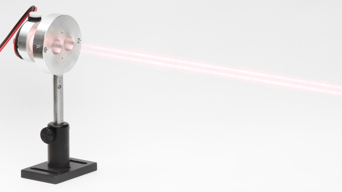 This photo shows the front view of the Zeiss OPMI laser collimator with the beams energized. The beams emerge from the spherical mounts
and pass through the two large holes in the assembly.
The smaller holes near the edge accept 6mm cage mount rods
for attaching the collimator to the device under test. The laser pointer modules are wired in parallel and powered by a 3 volt battery source.
Fixturing may be attached via a 1/4-20 tripod mount on the bottom, which also accepts optical breadboard posts such as is shown here.
This photo shows the front view of the Zeiss OPMI laser collimator with the beams energized. The beams emerge from the spherical mounts
and pass through the two large holes in the assembly.
The smaller holes near the edge accept 6mm cage mount rods
for attaching the collimator to the device under test. The laser pointer modules are wired in parallel and powered by a 3 volt battery source.
Fixturing may be attached via a 1/4-20 tripod mount on the bottom, which also accepts optical breadboard posts such as is shown here.
This photograph exhibits the dodging technique for photographing laser beams.
It is actually two photos of the same scene, combined in Photoshop to create a double-exposure effect.
The first photo was with normal studio lighting and the camera tripod mounted.
The second photo was of the same scene, but a 30-second time exposure in a darkened room with the lasers energized.
During the 30 seconds I swept a handheld white card along the beams.
This essentially integrates a spatial map of many point samples.
See more about this beam-dodging photography technique on my optical prototyping page.
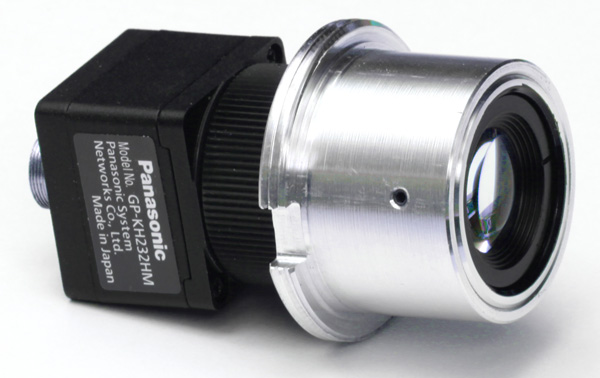 This adapter fits C-mount cameras to the Zeiss OPMI instruments, shown here with a typical camera, the Panasonic GP-KH232 high-definition module.
This camera provides 1080p HD video via a HDMI or RGB connection from a separate controller.
The rectangular body shown here is tiny, less than an inch-long cube.
The adapter is very compact due to its lack of a mirror diagonal, which mirroring is performed in the camera controller, a rare
but valuable feature for instrumentation cameras.
Various focal lengths can be fitted into this adapter to provide various crop ratios for different camera sensor sizes.
This photo shows the 35mm focal length version.
See detailed mechanical diagrams here for an updated design,
as well as the installation instructions.
This adapter fits C-mount cameras to the Zeiss OPMI instruments, shown here with a typical camera, the Panasonic GP-KH232 high-definition module.
This camera provides 1080p HD video via a HDMI or RGB connection from a separate controller.
The rectangular body shown here is tiny, less than an inch-long cube.
The adapter is very compact due to its lack of a mirror diagonal, which mirroring is performed in the camera controller, a rare
but valuable feature for instrumentation cameras.
Various focal lengths can be fitted into this adapter to provide various crop ratios for different camera sensor sizes.
This photo shows the 35mm focal length version.
See detailed mechanical diagrams here for an updated design,
as well as the installation instructions.
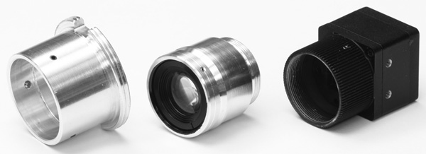 Here is the same adapter, showing its two components separated from the Panasonic GP-KH232 camera.
The middle component contains the focal lens cell with C-mount threads. This cell also provides focus calibration and
image centering adjustments. The sleeve on the left fits the Zeiss OPMI accessory fitting and also provides rotational alignment
of the camera, since C-mount threads stop at a random orientation and do not align rotationally.
Here is the same adapter, showing its two components separated from the Panasonic GP-KH232 camera.
The middle component contains the focal lens cell with C-mount threads. This cell also provides focus calibration and
image centering adjustments. The sleeve on the left fits the Zeiss OPMI accessory fitting and also provides rotational alignment
of the camera, since C-mount threads stop at a random orientation and do not align rotationally.
The Panasonic GP-KH232 camera (details)
is based on the Sony IMX036 HD video chip
(details).
Other C-mount instrumentation cameras using this chip include the Point Grey Flea 3, a USB 3.0 interfaced camera
(details)
, and the Leopard Imaging
LNC-Q10 H.264 Ethernet/wireless camera (details).
The current version of this adapter fits the Panasonic GP-US932A HD Series C-mount cameras.
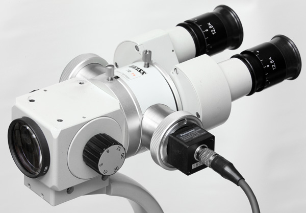 This shows the adapter and camera mounted on an Zeiss OPMI beamsplitter on a Zeiss 125/16 slit lamp.
The same accessory fittings and beamsplitter are used on Zeiss operating microscopes.
The adapter shown here (25mm focal length) nests entirely within the OPMI fitting, as does the camera's turret, leaving only about
an inch of the tiny camera projecting out from the beamsplitter. The cable runs to a separate controller box which provides HD video signals
for live display on a standard HDTV and/or digital recording.
This shows the adapter and camera mounted on an Zeiss OPMI beamsplitter on a Zeiss 125/16 slit lamp.
The same accessory fittings and beamsplitter are used on Zeiss operating microscopes.
The adapter shown here (25mm focal length) nests entirely within the OPMI fitting, as does the camera's turret, leaving only about
an inch of the tiny camera projecting out from the beamsplitter. The cable runs to a separate controller box which provides HD video signals
for live display on a standard HDTV and/or digital recording.
See additional photos on the Zeiss OPMI to C-mount adapters.
See also the detailed assembly diagram [PDF file].
Panasonic HD Video Camera Adapter for Zeiss OPMI and Möller instruments
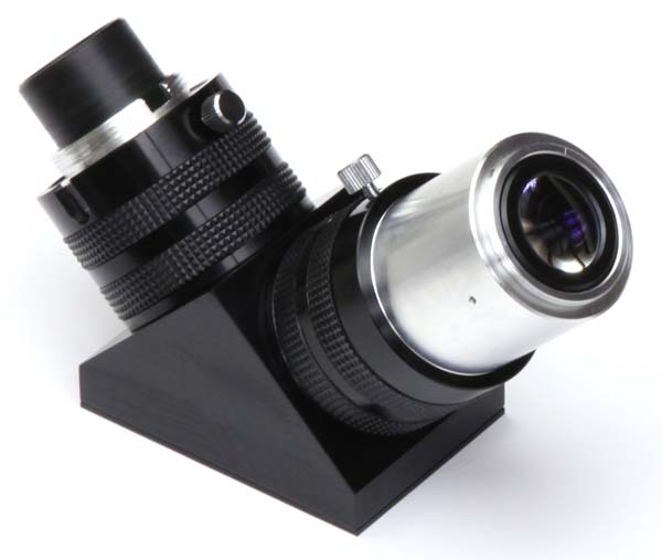 This adapter connects a Panasonic HD video medical camera (Panasonic model AG-MDC10 camera with AG-MDR15 recorder) to Zeiss OPMI instruments.
More photos for this Zeiss project are here.
This same adapter principle can adapt the Panasonic professional video camera AG-HCK10G (with AG-HMR10 recorder) to various
microscopic instruments for non-medical applications.
This adapter connects a Panasonic HD video medical camera (Panasonic model AG-MDC10 camera with AG-MDR15 recorder) to Zeiss OPMI instruments.
More photos for this Zeiss project are here.
This same adapter principle can adapt the Panasonic professional video camera AG-HCK10G (with AG-HMR10 recorder) to various
microscopic instruments for non-medical applications.
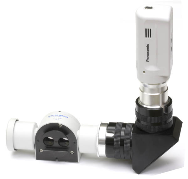 This is the same type adapter, except fitted for a Möller-Wedel surgical microscope beamsplitter, shown with the
medical Panasonic AG-MDC10 HD video camera.
More photos for this Möller project are here.
This is the same type adapter, except fitted for a Möller-Wedel surgical microscope beamsplitter, shown with the
medical Panasonic AG-MDC10 HD video camera.
More photos for this Möller project are here.
Modifying the Microsoft Lifecam Cinema and Lifecam Studio for Instrumentation Applications
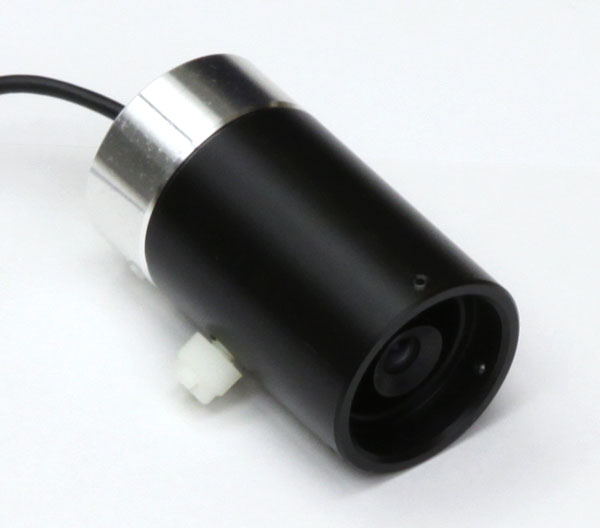 At left is an example of how I modify the the Microsoft Lifecam Cinema (720p HD) and Microsoft Lifecam Studio (1080p HD) cameras
for scientific and medical instrumentation.
The Lifecams are USB cameras with amazing high-definition video performance, especially considering their street price of about $50 to $100.
They also have the rare virtue among webcams of being housed in a cylindrical metal shell,
so they can be easily fitted into the cylindrical geometry typical of optical instrumentation,
in many cases with no modifications, using a relatively simple mechanical adapter.
Compare this to the format of the GoPro HD Hero portable cameras, which are larger and rectangular,
and not readily modified, optically or mechanically.
At left is an example of how I modify the the Microsoft Lifecam Cinema (720p HD) and Microsoft Lifecam Studio (1080p HD) cameras
for scientific and medical instrumentation.
The Lifecams are USB cameras with amazing high-definition video performance, especially considering their street price of about $50 to $100.
They also have the rare virtue among webcams of being housed in a cylindrical metal shell,
so they can be easily fitted into the cylindrical geometry typical of optical instrumentation,
in many cases with no modifications, using a relatively simple mechanical adapter.
Compare this to the format of the GoPro HD Hero portable cameras, which are larger and rectangular,
and not readily modified, optically or mechanically.
The most valuable potential is that the Lifecam cameras, when disassembled for the "guts", can be placed into custom housings with
new lenses or no lenses at all, a technique which I have developed after amateur astronomer Gary Honis.
For example, the assembly shown in the photo uses a modified Lifecam with custom lens assembly
to turn an ordinary handheld ophthalmoscope into a digital retinal camera.
The original Lifecam lens is of very high quality but nevertheless provides only
a very wide-angle field of view not suited to most instrumentation purposes.
I remove this original lens and substitute a custom fitting for stock M12 lenses or C-mount lenses.
This converts the Lifecam into a configurable fixed-focal-length HD camera for fitting with infinity, macro, or microscopic optics.
The entrance pupil collimates to any visual eyepiece, even very short eye-relief eyepieces
that would vignette with the usual digital camera lenses.
Removing the lens and substituting an appropriate custom mechanical fitting, such as a C-mount receptacle,
yields a camera for direct projection with a format of 1/4" (Lifecam Cinema) or 1/2.7" (Lifecam Studio).
The camera then becomes a direct HD replacement for older 1/4" or 1/3" SD (standard-definition NTSC or PAL) video cameras.
The Lifecams are thus seen to be a versatile and cost-effective basis for imaging, but they do have several limitations.
While they produce HD format video, they do not produce any standard video output signal such as HDMI.
Instead they are USB-only devices which must be tethered to a Windows computer with Microsoft's proprietary driver to view or record the images.
The video/still viewing/recording application Microsoft provides is not very sophisticated,
but the camera hardware drivers are properly implemented so that they
work with standard video and studio applications such as National Instruments Labview,
Adobe Premier,
and the free and essential gem called virtualdub.
The power consumption of these cameras is such that they must be housed in metal fittings which act as a heat sink.
To dissipate heat they also cannot be located completely inside of closed assemblies without a provision for external cooling.
Normally with any CCD camera one must block infrared to avoid unintended lens aberrations and unnatural color in the image.
The original lens of the Lifecam contains an integral infrared blocking filter (IR cut filter), so when replacing the lens one must
typically provide an IR cut filter for visible light applications; otherwise one has an near-infrared-sensitive camera.
Should IR response be desirable, then removing the original lens and filter may be appropriate.
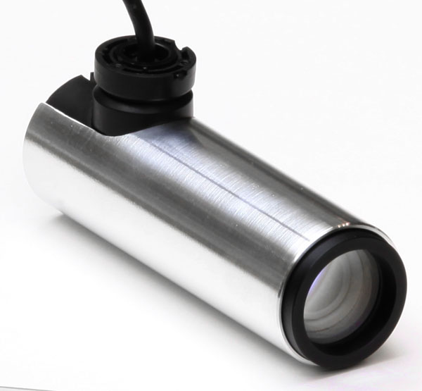 This is again the Microsoft LifeCam Studio 1080p HD camera,
which I have modified by removing the stock exterior and replacing it with a custom metal sleeve,
and replacing the stock wide-angle lens with a 50mm f/2 telephoto lens adjusted to a close focus, yielding a macro zoom effect.
This lens provides a 55mm wide by 31mm high (2.2 by 1.2 inches) field of view at 500mm (20 inches),
comparable to a 400mm lens on a 35mm format camera.
The assembly is about 30mm (1.2 inches) diameter by 90mm (3.5 inches) long, weighing but a few ounces.
The intended application is an eyeglass-mounted HD video recorder for surgical or laboratory procedures.
In microscopic terms, the resolution is a remarkable 10 lp/mm at a working distance of 500mm, many times better
than unaided visual resolution, making the enlarged HD display of the scene photo-realistic.
This is again the Microsoft LifeCam Studio 1080p HD camera,
which I have modified by removing the stock exterior and replacing it with a custom metal sleeve,
and replacing the stock wide-angle lens with a 50mm f/2 telephoto lens adjusted to a close focus, yielding a macro zoom effect.
This lens provides a 55mm wide by 31mm high (2.2 by 1.2 inches) field of view at 500mm (20 inches),
comparable to a 400mm lens on a 35mm format camera.
The assembly is about 30mm (1.2 inches) diameter by 90mm (3.5 inches) long, weighing but a few ounces.
The intended application is an eyeglass-mounted HD video recorder for surgical or laboratory procedures.
In microscopic terms, the resolution is a remarkable 10 lp/mm at a working distance of 500mm, many times better
than unaided visual resolution, making the enlarged HD display of the scene photo-realistic.
Canon Viewfinder Magnifier-Inverter
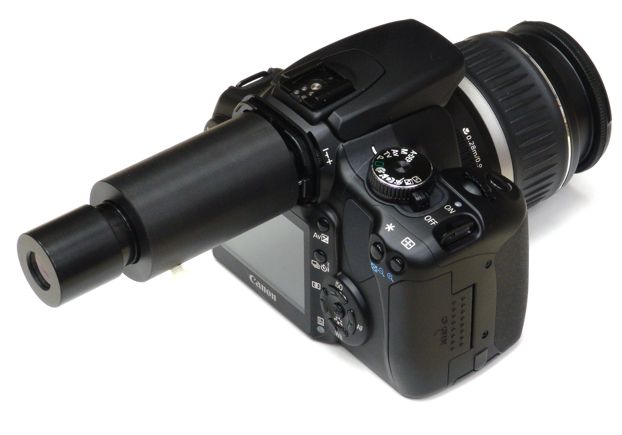 This viewfinder magnifier (see detailed description page) for Canon digital SLR cameras
is a custom telescopic component I make, which provides a 2X magnified and inverted enlargement of the standard viewfinder.
This is designed to compensate for the inverted view resulting from adaptation of certain instruments, such as the direct coupling
to a Topcon TRC-50VT retinal camera described above.
This viewfinder magnifier (see detailed description page) for Canon digital SLR cameras
is a custom telescopic component I make, which provides a 2X magnified and inverted enlargement of the standard viewfinder.
This is designed to compensate for the inverted view resulting from adaptation of certain instruments, such as the direct coupling
to a Topcon TRC-50VT retinal camera described above.
Topcon TRC-JE and TRC-FE Retinal Cameras
 This custom adapter retrofits a Topcon retinal camera to use a Canon or Nikon digital SLR camera instead of the original
Topcon 35mm film camera. Pictures and technical details are in the
installation instructions for Canon cameras [826 KB PDF file]
and installation instructions for Nikon cameras [298 KB PDF file].
You can also order online.
This custom adapter retrofits a Topcon retinal camera to use a Canon or Nikon digital SLR camera instead of the original
Topcon 35mm film camera. Pictures and technical details are in the
installation instructions for Canon cameras [826 KB PDF file]
and installation instructions for Nikon cameras [298 KB PDF file].
You can also order online.
A peculiarity of retinal camera optics is that the image produced by the instrument is upright, while a normal
camera lens produces an inverted image.
A specially modified SLR film camera back was therefore part of the original retinal camera system
This special camera provided a non-inverting, periscopic, mirror-mirror type viewfinder.
Ordinary SLR cameras provide a mirror-pentaprism type viewfinder, which inverts the incoming image,
the net result then being an upright view when an ordinary camera lens is attached.
Putting a digital SLR camera with conventional viewfinder on a retinal camera results in an inverted view in the viewfinder.
Some photographers simply accommodate this inversion,
or optionally my inverting viewfinder magnifier can be attached to provide
an upright view.
Topcon also configured variations of this instrument designated as TRC-FET, TRC-FET3, and TRC-FE3,
depending on whether it was equipped to for fluorescein angiography in addition to color photography ("F"),
whether the camera mount tilted on a pitch axis ("T"), or whether the instrument had a
power supply capable of fast exposure repetition with high flash energy ("3").
All variations are suitable for digital upgrade.
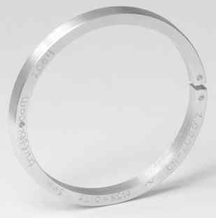 This thin threaded bushing adapts a 2"-40 threaded instrument to a M58x0.75 lens thread.
Note the split ring design which prevents seizing of the small pitch inside threads on the large outside diameter instrument.
Note also the small dimples (1/16" diameter x 1/16" deep) for a spanner wrench tool to insert and remove the adapter.
This thin threaded bushing adapts a 2"-40 threaded instrument to a M58x0.75 lens thread.
Note the split ring design which prevents seizing of the small pitch inside threads on the large outside diameter instrument.
Note also the small dimples (1/16" diameter x 1/16" deep) for a spanner wrench tool to insert and remove the adapter.
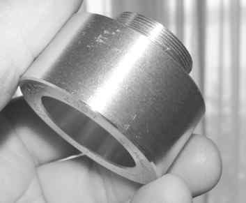 This is a custom adapter for a 1.162" outside diameter Bausch & Lomb eyepiece to C-mount (1"-32) lens thread.
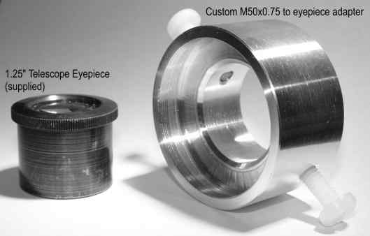 This is a custom adapter for a 1.25" outside diameter telescope eyepiece to an M50x0.75 lens thread.
Opposing Nylon thumbscrews lock the eyepiece in position, while allowing vertex distance adjustment.
This is a custom adapter for a 1.25" outside diameter telescope eyepiece to an M50x0.75 lens thread.
Opposing Nylon thumbscrews lock the eyepiece in position, while allowing vertex distance adjustment.
Selecting a Camera for Digital Photomicrography
I've had inquiries about what "consumer" or "prosumer" digital cameras are good for adapting to
photomicrography. Some criteria of desirability are:
- Accessory threads that permit flush mounting of an adapter:
Sadly, current digital cameras such as the compact consumer types have almost all eliminated this feature in recent years.
Such threads used to be more commonly provided for the mounting of filters on the front of the camera lens, but
this option has apparently become unimportant to casual point-and-shoot photographers.
Some cameras with turret type lenses have threads or a bayonet fitting on the camera body
which accepts a special adapter tube which surrounds the turret and terminates in standard
filter threads; this is an acceptable compromise.
This tube is often called a "conversion lens adapter" (CLA) because it it meant to be used to attach a "conversion lens",
A "conversion lens" is essentially a short Galilean telescope which you attach in front of the normal camera lens
to increase the magnification and thus convert the effective focal length of the built-in lens for a telephoto effect.
One can also make this Galilean telescope with less than 1X magnification, and thus decrease the effective focal
length and obtain a wide-angle, fisheye effect. Since the manufacturers typically use a standard filter thread size,
these tubes are suitable for attaching filters and microscope adapters.
-
Optical dimensions close to the human eye: This permits a direct optical path for
through-the-eyepiece afocal coupling, and avoids vignetting.
See the section on Understanding and Avoiding Vignetting below.
Large lenses, such as are found on better snapshot cameras and SLRs, have a deeply entocentric entrance pupil which
introduces unavoidable vignetting in an attempt at
afocal photomicrography; such camera lenses can only be adapted with
a photo eyepiece, which is a more expensive adapter incorporating optical elements.
Inexpensive cameras today tend to have the appropriate lens pupil in a turret form, but lack accessory threads.
-
Manual modes for aperture, shutter, and focus:
Afocal photomicrography typically requires that the aperture be manually fixed, since wider aperture sizes
may introduce vignetting.
Manual shutter control is not strictly necessary, but it is convenient for adjusting the
exposure of difficult microscopic scenes.
Focusing is best accomplished by the manual instrument adjustments, not by hunting with the camera's autofocus algorithm.
Inexpensive digital cameras today typically provide such a manual mode, although this was not the case during
the early years of digital photography.
What cameras sold today are suitable?
Cameras at very low cost (less than USD $200) have become available
which meet all the above desirability criteria.
The Canon A630 is an example of an ideal camera for digital photomicrography.
It also provides a live video-out preview, so you can then attach a video monitor to your instrument.
Canon changes models very frequently, and in 2013, the point-and-shoot models with suitable features are the following
from the A-series, G-series, and S-series models:
Canon Point-and-Shoot Cameras Suitable for Eyepiece Photomicrography
Model list updated as of May, 2013
Most of the models listed are older and not currently sold new by Canon
(But used specimens are widely and cheaply available)
|
|
Canon Model
[Note 1] | Articulated
LCD screen | LCD
Size | Remote Capture
[Note 2] | Live Video
NTSC/PAL | Canon
CLA tube | Aftermarket
CLA tube(s)
[Note 3] |
|---|
|
| Canon A510 | No | 1.8" | Yes | Yes | LA-DC52F | Bower A52B510C
Sakar JA-A80-52 |
| Canon A520 | No | 1.8" | Yes | Yes | LA-DC52F | Bower A52B510C
Sakar JA-A80-52 |
| Canon A540 | No | 2.5" | No | Yes | LA-DC52F | Bower A52B510C
Sakar JA-A80-52 |
| Canon A570 IS | No | 2.5" | No | Yes | LA-DC52G | Sakar JA-A570-52 |
| Canon A580 | No | 2.5" | No | Yes | LA-DC52G | Sakar JA-A570-52 |
| Canon A590 IS | No | 2.5" | No | Yes | LA-DC52G | Sakar JA-A570-52 |
| Canon A610 | Yes | 2.0" | No | Yes | LA-DC58F | Bower A52B610C
Sakar JA-640-52 |
| Canon A620 | Yes | 2.0" | Yes | Yes | LA-DC58F | Bower A52B610C
Sakar JA-640-52 |
| Canon A630 | Yes | 2.5" | No | Yes | LA-DC58F | Bower A52B610C
Sakar JA-640-52 |
| Canon A640 | Yes | 2.5" | Yes | Yes | LA-DC58F | Bower A52B610C
Sakar JA-640-52 |
| Canon A650 IS | Yes | 2.5" | No | Yes | LA-DC58J | |
| Canon A700 | No | 2.5" | No | Yes | LA-DC58G | |
| Canon A710 IS | No | 2.5" | No | Yes | LA-DC58G | |
| Canon A720 IS | No | 2.5" | No | Yes | LA-DC58G | |
| Canon G3 | Yes | 1.8" | | | LA-DC58B | |
| Canon G5 | Yes | 1.8" | | | LA-DC58B | |
| Canon G6 | Yes | 2.5" | | | LA-DC58D | |
| Canon G7 | No | 2.5" | Yes | Yes | LA-DC58H | Sakar JA-G7-58 |
| Canon G9 | No | 2.5" | Yes | Yes | LA-DC58H | Sakar JA-G7-58 |
| Canon G10 | No | 3.0" | Yes | Yes | LA-DC58K | Sakar LA-G10 |
| Canon G11 | Yes | 2.8" | No [Note 6] | Yes | LA-DC58K | Sakar LA-G10 |
| Canon G12 | Yes | 2.8" | No [Note 6] | Yes, also 720p
HDMI playback | LA-DC58K | Sakar LA-G10 |
| Canon S2 [Note 4] | Yes | 1.8" | Yes | Yes | LA-DC58E | |
| Canon S3 [Note 4] | Yes | 2.0" | Yes | Yes | LA-DC58E | |
| Canon S5 [Note 4] | Yes | 2.5" | Yes | Yes | LA-DC58E | |
| Canon S90 | No | 3.0" | No | Yes | None | Lensmate 37mm adapter |
| Canon S95 | No | 3.0" | No | Yes, also 720p HDMI | None | Lensmate 37mm adapter |
| Canon SX1 [Note 5] | Yes | 2.8" | No | No
(records HD) | None | Lensmate 58mm adapter |
| Canon SX10 [Note 5] | Yes | 2.5" | No | No
(records SD) | None | Lensmate 58mm adapter |
| Canon SX20 [Note 5] | Yes | 2.5" | No | No
(records HD) | None | Lensmate 58mm adapter |
| Canon SX30 [Note 5] | Yes | 2.7" | No | No
(records 720p HD) | None | Lensmate 58mm adapter |
| Canon SX40 [Note 5] | Yes | 2.7" | No | SD only
(records 1080p HD) | None | Lensmate 58mm adapter |
|
Canon models A460, A470, A530, A550, and A560 are not suitable (lens-adapter bayonet omitted).
Likewise all SD and most SX models
(except as listed above). Sorry!
However, see my custom adaptation of the SD750 and SD790 above.
After 2009, no Canon point-and-shoot camera provided an accessory fitting except the Canon G11/G12!
|
|
| Older Canon models A80 and A95 are suitable via the LA-DC52F CLA tube. |
Note 1: Don't be confused by the "IS" designation appended to some Canon model numbers.
This is just a redundant emphasis for the image stabilization feature and does not
distinguish a model variation.
For example, you may see the Canon A650 camera
referred to as model A650 IS, A650-IS, A650IS, or just A650; these are all the same camera.
Note 2: Remote capture requires a software application for the PC.
Canon includes a basic remote capture application with the camera.
Breeze Systems publishes PSRemote for $49 (USD).
Note 3: Every aftermarket CLA tube I've seen is made of sturdy metal, fits well, and costs less
than Canon's all-plastic originals. Brands like Bower, Sakar, and Kenko are all well-made,
precisely fitted, and generally quite suitable.
Note 4: Canon models S2, S3, and S5 have a deep entrance pupil which will couple only to high-eyepoint eyepieces (eyepieces with
eye relief of 18mm or more). Shorter eye relief eyepieces will exhibit vignetting.
Note 5: Canon SX models do not provide filter threads or a CLA bayonet, but they
do provide a hood bayonet at the end of the lens which can accept an aftermarket adapter (linked in
the table above).
Canon does not offer anything but a plastic glare hood for this bayonet fitting.
Note 6: Canon apparently dropped remote-capture support in the G11 and G12 models, after providing
it in the G-series up to and including the model G10.
See the PSRemote features list.
The articulated LCD screen is a useful feature if the camera
must be mounted at an angle that does not permit convenient viewing towards the rear of the camera body.
Remote capture which allows you to operate the camera
tethered to a PC, which can be an important feature for applications like laboratory data capture.
A video-out feature allows you to display the live (although low-resolution) microscopic image on a video monitor or PC, such as for
group instruction.
You may also wish to study the eyepiece adapter instruction sheet provided with my
eyepiece adapters for the Canon A-series cameras.
For laboratory use, it is often necessary to have direct PC control of
the camera, and/or image transfer, via protocols over USB connections like PTP (Picture Transfer Protocol).
This allows periodic or time-based taking of photos, or synchronization with other laboratory apparatus or
sensors.
See Figuiéres excellent page on
Digital Camera Support for UNIX, Linux and BSD.
Understanding and Avoiding Vignetting
The "exit pupil" produced by the microscope eyepiece is the small circular aperture image formed
some distance (the vertex or eye-relief distance) above the top of the eyepiece.
In the early days of microscopy before modern optical engineering, the exit pupil was known as the
"Ramsden disc" or "Ramsden circle", after the disc of light which is formed when the objective is diffusely illuminated.
This disc is typically about 18mm above the eyepiece, which you can visualize by holding a white card above the eyepiece
while examining a bright subject in the microscope.
The exit pupil is a critical characteristic for analyzing any optical system, and especially important
when coupling two optical systems to each other, such as the eye to the microscope, or a camera to the microscope.
To avoid vignetting in afocal coupling, the camera's entrance pupil must be aligned with the exit pupil of the eyepiece,
Since the eyepiece is "pericentric" (that is, its exit pupil is located outside the last surface of the eyepiece)
while the typical camera lens is "entocentric" (that is, its entrance pupil is some distance inside the front surface of the lens),
this alignment may or may not be possible, depending on the distances of these pupils from their respective surfaces.
Another way to state this non-vignetting condition is: the pericentricity of the eyepiece must equal or exceed the
entocentricity of the camera lens.
You can think of the eyepiece exit pupil as a virtual keyhole through which you must look to see the microscope field of view,
and likewise the camera's entrance pupil as a virtual keyhole through which light must pass to reach the
camera's digital image sensor (or film frame in the old days).
To avoid vignetting, these two keyholes must overlay each other
by locating in the same position along the optical axis.
If these two pupils are mismatched, being placed at different axial locations,
the camera will see a vignetted image, just like looking into a microscope with your eye too close to or too far away from the eyepiece
shows you a vignetted image.
Vignetting appears as either "too far" (the
camera "sees" only the center of the field, because an aperture in the eyepiece masks the edges) or
"too close" (the camera can potentially "see" the whole field, but the image sensor crops the edges).
This is also rather like an impedance matching problem in electronics.
The axial distance constraint is typically
incompatible with a camera lens that establishes an entrance pupil
deep within the lens itself, which is typical of large complex lenses
such as are found on DSLRs. The eyepiece "eye relief" (distance of the eyepiece's exit pupil from the last surface of the eyepiece, 20mm or so typical) is designed to
be long enough to at least reach through the human cornea and anterior chamber
of the eye to the iris, which constitutes the eye's entrance pupil.
An eyepiece with a generous eye relief
will provide enough of this distance to allow you to wear eyeglasses and still place
your iris up to the exit pupil of the eyepiece.
When imaging with a camera instead of the human eye,
this same eye relief must reach far enough into the camera lens to
reach the camera's entrance pupil. That is, the eyepiece provides ample "eye
relief" for human eyes, but this may or may not be enough "relief" for the camera lens system.
Some cameras have lens dimensions and entrance pupils similar to the human eye,
and thus are well-suited to afocal photomicrography because the eyepiece exit pupil
can reach the camera entrance pupil, and the pupils are of similar size.
Other cameras, especially expensive DSLRs with big lenses, are severely
mismatched in this regard, and impose intolerable vignetting.
The entrance pupil of a large camera lens is typically itself large and/or deep within the lens body,
in comparison the scale of the human eye.
In terms of typical dimensions, a typical 10X wide-field eyepiece exit pupil is sized as a
disk of about 10mm diameter floating about 20mm above the eyepiece, while a typical large camera lens has an entrance pupil
35mm or more in diameter, located 50mm or so inside of the first glass surface.
While the f/stop setting of the lens can shrink the camera's entrance pupil, and the zoom adjustment can
move the entrance pupil somewhat forward and back, there is typically not enough range of freedom to
provide a match.
Think of it as a horse or a whale trying to look into your microscope; their large
eyes would see a vignetted image in a human-scale eyepiece that is too small for their eyes.
If the camera lens can't be changed (which is the case with consumer type
cameras that have permanently mounted lenses), the most practical thing
is to replace the stock microscope eyepiece with a gigantic, wide-field, low-power, eyepiece.
Such an eyepiece provides a very large exit pupil, very long eye relief, and insensitivity
to lateral pupil shift. This is the approach of my latest design for a custom
fitted adapter with 30 or 50 mm diameter symmetric lens aperture.
The disadvantages of the "giant eyepiece" approach include the cost of this massive eyepiece, and that
the size and weight of the resulting eyepiece-camera combination tend
to overwhelm a typical microscope, requiring some type of auxiliary
mechanical support. Some older microscopes correct objective aberrations in the
eyepiece, and this correction is not feasible in a reasonably-priced custom eyepiece.
Testing camera compatibility at the camera store:
It would be very useful to be able to test cameras for afocal compatibility with a given microscope
without having to carry the entire microscope to the camera store (although I have done that, to strange looks!).
Unfortunately you cannot test cameras for vignetting by carrying just the loose eyepiece in hand to the camera store
and holding the eyepiece up to various cameras. Why?
In a compound microscope, the exit pupil of the eyepiece is actually the image of the aperture stop
of the selected objective, as formed by the optics of the eyepiece.
This exit pupil is what potentially causes vignetting, but the exit pupil disappears when the eyepiece is taken
off the microscope.
A given camera may be able to see the full field in the loose eyepiece without vignetting,
but when placed on a microscope a further stop is imposed which may cause vignetting.
To test cameras with just an eyepiece and not the entire large microscope at hand,
one could cleverly simulate this exit pupil by improvising
a stopped paper tube to slip onto the eyepiece. This tube would end in an aperture of size about
that of the smallest aperture of the objectives (most commonly, a few mm),
at the approximate apparent distance of the objective normally from the eyepiece (most commonly, 160mm).
Black construction paper and Scotch tape would be suitable materials to use.
This will yield an assembly about 8 inches long.
Peering into the eyepiece toward a bright, diffuse light will reveal the familiar appearance of the eye's
alignment and vignetting, as if the eyepiece were on the microscope, except the field of view is diffusely lit instead of
displaying an image.
One could carry this easily portable assembly to the store for testing cameras.
"Vignetting" is a broad effect in optics that involves more than just instrument-to-camera couplings.
We have been using the word "vignetting" to describe an undesirable mismatch of camera to instrument, resulting
in either a loss of some of the instrument's field of view, or a failure to fill the camera's field of view, or both.
Another sense of the word "vignetting" involves the unavoidable darkening of image fields at the edges due
to natural or optical principles.
For example, natural vignetting is the effect in multi-element lenses of the entrance
pupil being gradually blocked by prior apertures at angles off the optical axis, which can be avoided altogether
in a careful lens design, but is typically tolerated as a compromise in wide-angle or zoom lenses.
This effect is observed as a drop-off in brightness at the edges of an image, and as
the gradual distortion of off-center out-of-focus-highlights from round into a cat's-eye shape.
Vignetting is discussed in some optical textbooks under the "Theory of stops" (Jacobs, Fundamentals of Optical Engineering),
"Effects of stops" (Jenkins and White, Fundamentals of Optics), or "Stops and apertures" (Smith,
Modern Optical Engineering).
Yet another sense of "vignetting" is a certain fundamental optical limitation:
optical vignetting is the unavoidable drop-off in intensity at an image field by the fourth power of the
cosine of the angle of incidence (the cosine4 falloff).
Using the term "vignetting" for this effect would seem to be a misnomer,
since this falloff has nothing to do with stops and is unavoidable.
Since the visual appearance resembles vignetting due to stops, the term has nevertheless been applied.
"Vignetting" is of course also a style of the photographic arts,
where stop-induced vignetting is deliberately applied to a photograph.
The edges of a portrait or scene become gradually darkened or washed-out,
enhancing the composition with a tunnel-vision effect.
Understanding C-Mount and CS-Mount Standard Mechanics, Optics, and Cameras
The C-mount standard
is a widely-used method of connecting connecting small
cameras to lenses, such as mounting a lens on an industrial camera, or for connecting trinocular phototubes on microscopes to cameras.
The "C" is said to stand for "cine", the original application being 16mm movie camera lenses, such as were made by
Arri, Bolex, Angenieux, Bell & Howell, and Eclair.
The C-mount standard specifies both the optical and mechanical details for the optical source (such as a lens or microscope) and optical receiver (such as a still camera or TV tube).
The optical source side consists of a tube concentric with the optical axis, ending in a 1"-32 male thread, projecting from a
larger flange (typically 30mm OD or more) perpendicular to the axis.
The inside diameter of this tube can vary, but practically speaking, an ID of about 0.9 inches is an upper
limit to provide enough metal beneath the threads for mechanical strength in the tube.
The projection of the male threaded portion from the flange is 4mm (0.157"), and
the depth of female threading is 4.5mm (0.177");
the slightly longer female length ensures the male insertion does not "bottom out".
Many cameras accept up to 8mm for the threaded portion instead of just 4mm, since 4mm is only about 5 threads
of a 32 tpi pitch, and at least 2 of these 5 threads must be relieved for runout up to the shoulder in
single-point threading on a lathe, leaving only 2 or 3 fully engaged threads between the components, but
a lens with longer male threads would be non-standard.
The light rays of the optical source form an image plane
0.69 inch (17.526mm) away (C-mount) or 12.52mm (CS-mount) from this flange (called the "flange-back" distance), with the circular image field
being about 18mm diameter. The optical receiver consists mechanically of a 1"-32 female thread,
with a detector and/or further optics based on the image location.
A CS-mount camera can work on a C-mount source by simply moving the camera out mechanically an extra 5mm with a male/female-threaded spacing ring.
Vice versa, a C-mount camera is too "nearsighted" for a CS-mount lens; without additional optics to relay the
image further down the optical axis, the lens image cannot reach the camera's focal plane.
C-mount "relay lenses" are short optical tubes with male and female C-mount threaded fittings,
and optical elements to shrink the image field size.
They are specified in terms of power, which ranges from 1.0X (no change in size, just an extension),
to fractions such as 0.63X or 0.5X. To apply a relay lens, one chooses the power to
shrink the diameter of the circular C-mount image field to fit the rectangular image sensor with a desirable crop.
For example, a typical image field diameter of 1/2" is much larger than a 1/3" CCD sensor (6mm diagonal),
so one could insert a 0.5X relay lens to shrink the image to 6.3mm, so that the CCD pixels would
almost completely span the image field. In theory, one could stack C-mount relay lenses to create
a combined relay lens producing the product of the individual magnification factors, if that were useful,
but the image degrades slightly with each intervening group of lenses.
The term "C-mount relay lens" is also used (confusingly) by some microscope manufacturers to refer to the fitting which
they provide to attach to a microscope's trinocular photo port and which ends in a C-mount standard thread and real image.
Since this is actually an adapter in the mechanical sense from the photo port mount (bayonet or thread) to C-mount thread,
it is not strictly a C-mount relay having C-mount threads on each end, nor is it a relay lens in the proper sense
of relaying an original focal image as another focal image elsewhere.
A typical example would be an Olympus 1X C-mount trinocular adapter, which is a hollow tube that fits a 30mm ID circular
photo port on one end, providing the C-mount male threads on the other end, with an overall length such that the microscopic
image plane meets the C-mount standard placement of 0.69 inches above the C-mount shoulder.
CCD cameras for C-mount applications are typically specified in terms of the CCD chip dimension.
Common sizes and image areas are:
Standard CCD Camera Sensor Sizes
Nominal versus Actual Dimensions
Standard Definition (SD) 4:3 Aspect Ratio
|
Nominal
Size | Actual Dimensions
Vertical x Horizontal | Diagonal
Dimension |
|---|
| 1/4" |
2.4mm x 3.2mm |
4.0mm |
| 1/3" |
3.6mm x 4.8mm |
6.0mm |
| 1/2" |
4.8mm x 6.4mm |
8.0mm |
| 2/3" |
6.6mm x 8.8mm |
11.0mm |
| 1" |
9.6mm x 12.8mm |
16.0mm |
The more recent 4/3 (four-thirds) digital camera standard proportionately specifies a 22mm image diagonal, where
various aspect ratios are possible. This proportions to a nominal 1.4" CCD. Digital SLR sensors in the Canon Rebel
series proportion to a nominal 1.7" CCD. Full-frame sensors like the Canon 5D Mark II proportion to a nominal
2.7" CCD (!). Hence digital SLR sensors are huge compared to the usual video camera CCDs that have been
fitted to microscopes and medical instruments in the past, and adapters must accommodate this large difference in scale.
High-definition cameras provide a 16:9 aspect ratio versus the 4:3 of standard definition.
The nominal sizes between SD and HD equate in the diagonal aspect of the chip, which is consistent
with the nominal size relating to the image circle produced by the lens.
With the different aspect ratios, the horizontal and vertical aspects for HD change as follows:
Standard CCD Camera Sensor Sizes
Nominal versus Actual Dimensions
High Definition (HD) 16:9 Aspect Ratio
|
Nominal
Size | Actual Dimensions
Vertical x Horizontal | Diagonal
Dimension |
|---|
| 1/4" |
1.96mm x 3.49mm |
4.0mm |
| 1/3" |
2.94mm x 5.23mm |
6.0mm |
| 1/2" |
3.92mm x 6.97mm |
8.0mm |
| 2/3" |
5.39mm x 9.59mm |
11.0mm |
| 1" |
7.8mm x 13.95mm |
16.0mm |
Magnification and 0.5X reduction:
I'm often asked to explain why ordinary C-mount video cameras are attached
to microscopes with adapters that reduce the magnification, such as a typical factor of 0.5X.
Understand that a microscope objective produces an circular, intermediate image of perhaps
18mm diameter (20mm or even 24mm in the more advanced designs),
which is what you are seeing when you view visually. The eyepiece is
just a strong magnifier with which you inspect this 18mm diameter image.
Since video camera sensor chips are only 5mm or 10mm across, if you place
the intermediate image directly onto the chip (called 1X magnification, or "direct projection"),
what the camera sees is then only a tightly cropped center portion of the
field of view you are used to seeing in the eyepieces, because you are
overlaying an 18mm circular image onto a much smaller rectangular sensor with perhaps a 9mm diagonal size (in a 1/3" format camera).
Applying a 0.5X reduction shrinks the microscope image down to a 9mm circle,
so the camera sees about the same field you see in the eyepieces, although
the eyepiece's field of view is circular and the camera's is rectangular,
so they can never truly match, being geometrically dissimilar.
A digital camera has a fixed spatial resolution in pixels, so if you
apply an 0.5X change to the microscope magnification, you have also cut
in half the spatial resolution of the camera at the subject, while doubling the
field of view. The camera yields the same number of pixels, and the same total resolution in the image,
but the image represents a larger subject area and a proportionately smaller spatial resolution of
the subject.
It helps to think of the microscope in reverse. Consider for example a typical 10X objective. Thinking in reverse, a 10X objective
effectively maps the camera chip to the subject with a 1/10th shrink. So a
digital camera with a typical 3.6mm x 4.8mm sensor chip, becomes 1/10th
that size, namely 0.36mm x 0.48mm (360 x 480 microns), in the world
of the microscope stage. If the camera chip provides, say, 1000 pixels across its 4.8mm width, then
each pixel samples light from an area of the subject of 480/1000 microns wide and high,
or about half a micron square. If you add an 0.5X lens in series with the 10X objective,
then the combined magnification (reduction in reverse) changes effectively to 5X (and 1/5th),
and each pixel is then collecting from about a micron square, while
the field of view is doubled in each direction.
You may also wish to study the C-mount adapter instruction sheet provided with my C-mount
products for point-and-shoot cameras.
Smaller mounting standards include S-mount (M12x0.5 thread) which used on many Web cameras (webcams, such as the Philips SPC900NC popular with astrophotographers,
and Philips Toucam Pro II PCVC840K, Toucam Pro PCVC740K, Toucam Fun PCVC730K, Toucam XS PCVC720K, Vesta Pro Scan PCVC690K, Vesta Pro PCVC680K, Vesta PCVC675K,
and Logitech Logitech Quickcam Pro 3000, 4000 and 5000)
and X-mount (M10x0.5 thread). (Maybe someone can tell me what the "S" and "X" mean in this context?)
There is an even smaller M8x0.35 thread mount for lenses, such as is used in the linear motor autofocusing mechanism
of the Microsoft Lifecam Cinema and Microsoft Webcam Studio webcams.
I have also seen reference to a Sony NF-mount, which appears similar to C-mount,
but with an M17x0.75 thread projecting 4mm, and a 12mm flange distance.
Certain video cameras made by Cohu provided a lens mount similar to C-mount but
using a larger 1.375"-32 thread, which was bushed down to C-mount size by a 0.350" long adapter.
The ENG lens mount is a three-eared bayonet type with hot-shoe connections,
used for high-end video cameras by manufacturers like Canon and Fujinon.
Sony video cameras such as the DXC-950P provide what Sony calls a "1/2-inch bayonet mount" for
lens attachment ("1/2-inch" referring to the camera's
CCD chip size for which the lens provides a field); this is another 3-eared bayonet with hot-shoe connections.
Sony also provides a "2/3-inch bayonet mount" with larger proportions for their 2/3" CCD cameras.
C-mount video camera microscope adapter
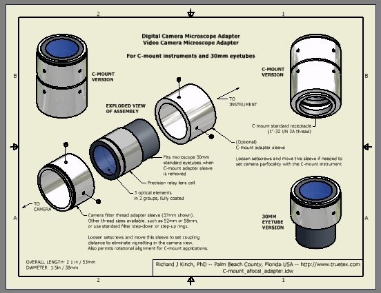 This assembly adapts a video camera or still camera to a microscope using
a C-mount interface, or a 23mm or 30mm standard eyetube. Optics in the adapter combine with the original camera lens to
create a relay lens system which scales the C-mount image to an appropriate smaller size for the very small imaging
chips in small camcorders.
The adapter fits high-definition video cameras such as the Canon HF20 and Canon HF200.
This is a versatile and economical approach to digital photomicroscopy, which provides 1080p high-definition live video,
digital video recording, and 3 megapixel still digital images, onto SD flash memory cards or directly to a tethered PC.
See the detailed drawing [616KB PDF file, 1 page] for a complete description.
This assembly adapts a video camera or still camera to a microscope using
a C-mount interface, or a 23mm or 30mm standard eyetube. Optics in the adapter combine with the original camera lens to
create a relay lens system which scales the C-mount image to an appropriate smaller size for the very small imaging
chips in small camcorders.
The adapter fits high-definition video cameras such as the Canon HF20 and Canon HF200.
This is a versatile and economical approach to digital photomicroscopy, which provides 1080p high-definition live video,
digital video recording, and 3 megapixel still digital images, onto SD flash memory cards or directly to a tethered PC.
See the detailed drawing [616KB PDF file, 1 page] for a complete description.
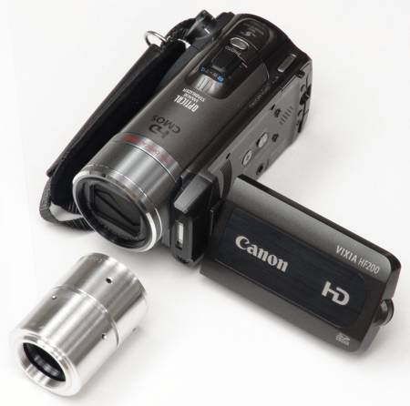 Here is a Canon HF200 video camera shown with the C-mount adapter ready to be attached.
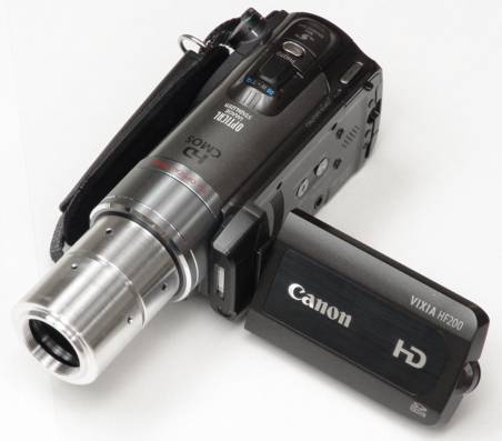 Canon HF200 video camera with the C-mount adapter attached.
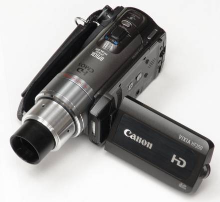 Canon HF200 video camera with 30mm eyetube adapter attached.
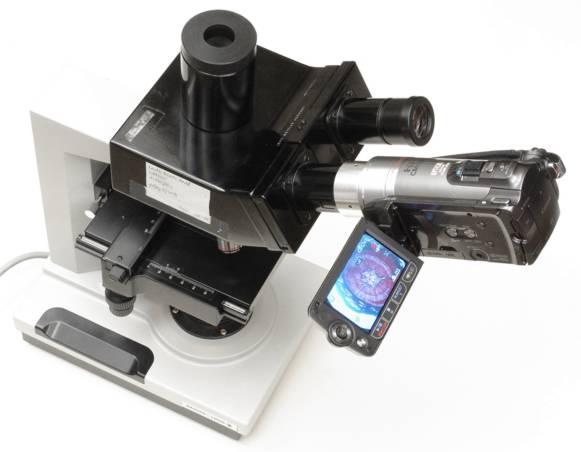 Canon HF200 video camera with the eyetube adapter in use on a microscope binocular.
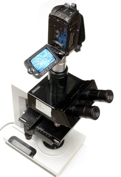 Canon HF200 video camera with the C-mount adapter in use on a microscope trinocular photo port.
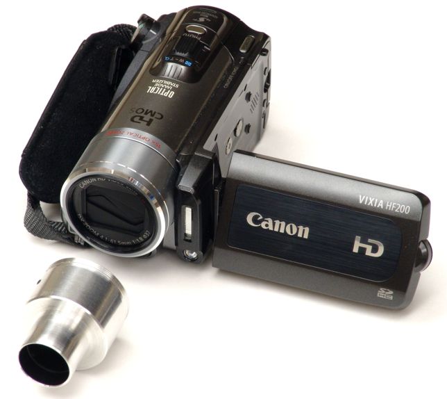 Canon HF200 video camera with 23mm eyetube adapter unattached.
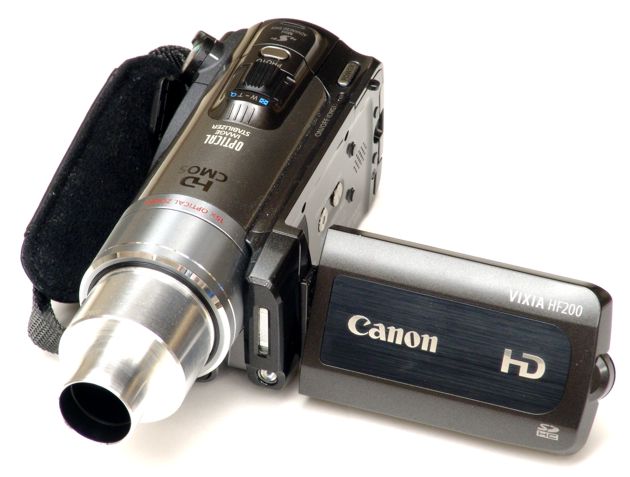 Canon HF200 video camera with 23mm eyetube adapter attached.
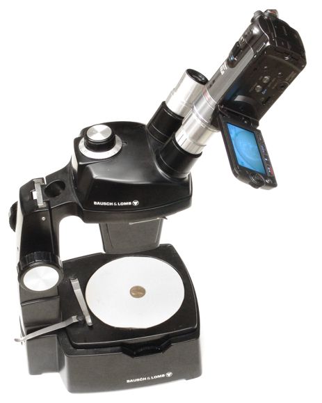 Canon HF200 video camera with the 23mm eyetube adapter in use on a Bausch and Lomb StereoZoom microscope binocular eyetube.
This method uses the standard eyetube and requires no special trinocular port for the digital camera,
and so fits a wide range of microscopes.
Canon HF200 video camera with the 23mm eyetube adapter in use on a Bausch and Lomb StereoZoom microscope binocular eyetube.
This method uses the standard eyetube and requires no special trinocular port for the digital camera,
and so fits a wide range of microscopes.
Microscope adapter for cameras and camcorders with large lenses
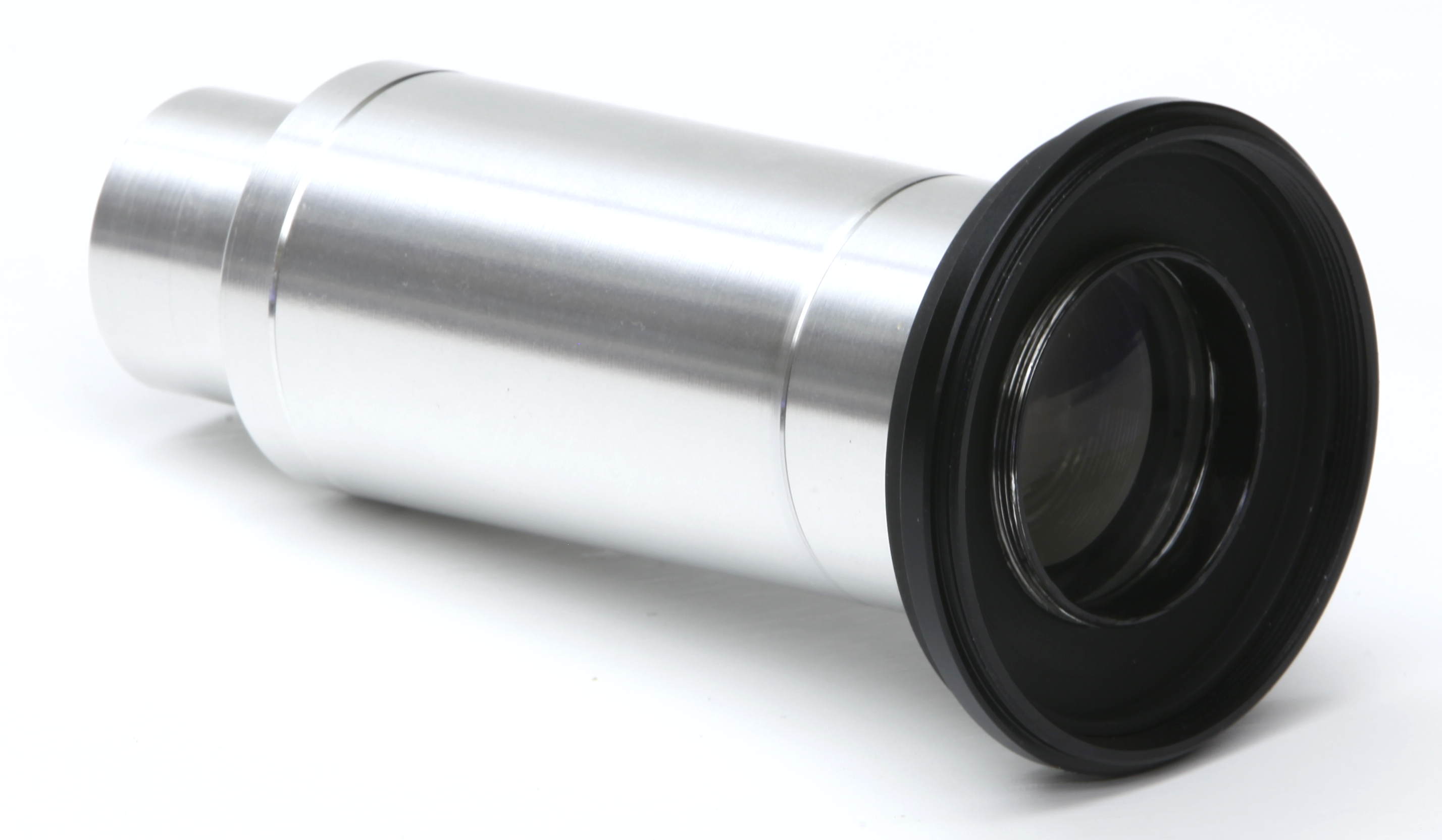 This adapter, improved in 2018 from my earlier designs, solves the problem of attaching larger format video cameras and camcorders
to microscope eyetubes or trinocular ports.
The zoom lenses on these cameras, compared to compact cameras, have pupils located far behind the front surface of the lens,
and will not mechanically couple to an ordinary eyepiece without vignetting the image.
This camera lens incompatibility is similar to an imaginary situation where you were wearing eyeglasses that sat several inches in front
of your eyes, which would not allow you to get close enough to the eyepiece to see the whole field of view provided in the eyepiece.
To solve this, the adapter incorporates wide-aperture optical elements to move the exit pupil several inches further back, while providing a
well-corrected afocal image. This type of adaptation allows you to exploit the camera's optical zoom capability to select a range of microscopic
image cropping desired in the camera's field of view,
an extra benefit compared to adapters that are fixed to operate at one specific cropping.
Designing zoom optics into microscopic adapters is costly and complex, while the mass-market cameras provide
high-quality zoom economically.
The adapter works well with high-end 4K camcorders that employ larger lens formats to gain true 4K lens resolution.
Full technical details and instructions for this adapter are here:
http://www.truetex.com/large_camera_lens_microscope_adapter.htm.
This adapter, improved in 2018 from my earlier designs, solves the problem of attaching larger format video cameras and camcorders
to microscope eyetubes or trinocular ports.
The zoom lenses on these cameras, compared to compact cameras, have pupils located far behind the front surface of the lens,
and will not mechanically couple to an ordinary eyepiece without vignetting the image.
This camera lens incompatibility is similar to an imaginary situation where you were wearing eyeglasses that sat several inches in front
of your eyes, which would not allow you to get close enough to the eyepiece to see the whole field of view provided in the eyepiece.
To solve this, the adapter incorporates wide-aperture optical elements to move the exit pupil several inches further back, while providing a
well-corrected afocal image. This type of adaptation allows you to exploit the camera's optical zoom capability to select a range of microscopic
image cropping desired in the camera's field of view,
an extra benefit compared to adapters that are fixed to operate at one specific cropping.
Designing zoom optics into microscopic adapters is costly and complex, while the mass-market cameras provide
high-quality zoom economically.
The adapter works well with high-end 4K camcorders that employ larger lens formats to gain true 4K lens resolution.
Full technical details and instructions for this adapter are here:
http://www.truetex.com/large_camera_lens_microscope_adapter.htm.
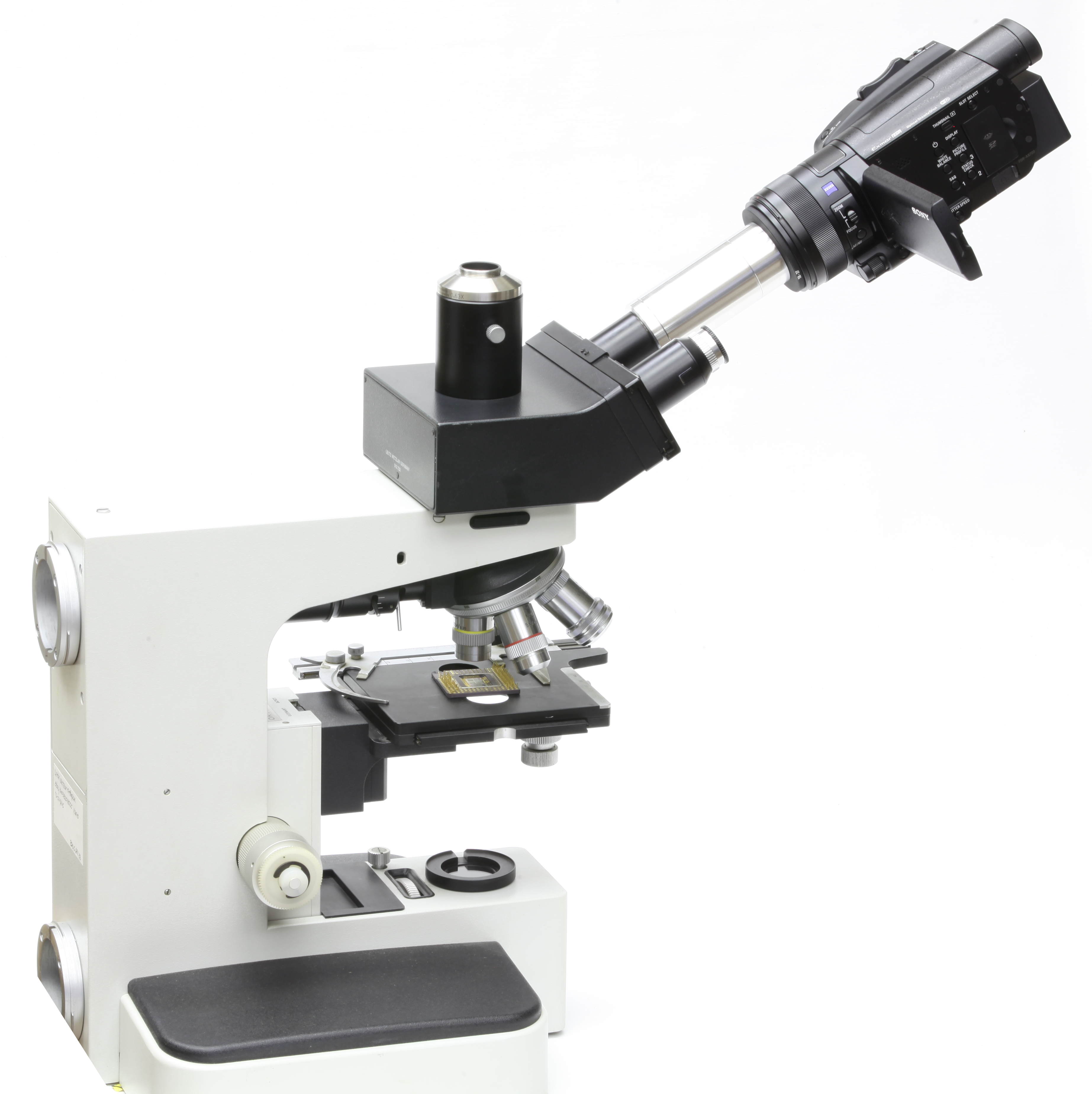 This is the large-lens adapter and camera (Sony FDR-AX700 4K) installed on a microscope (Leitz Orthoplan) eyetube.
C-mount adapter plate
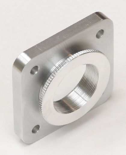 This photo shows my manufacture of a customer's design for a C-mount adapter.
This 2-part assembly accepts a C-mount lens and mounts it to a flat detector face.
The knurled, threaded bushing provides fine adjustment of the focal plane position.
This photo shows my manufacture of a customer's design for a C-mount adapter.
This 2-part assembly accepts a C-mount lens and mounts it to a flat detector face.
The knurled, threaded bushing provides fine adjustment of the focal plane position.
EF to C-mount adapter
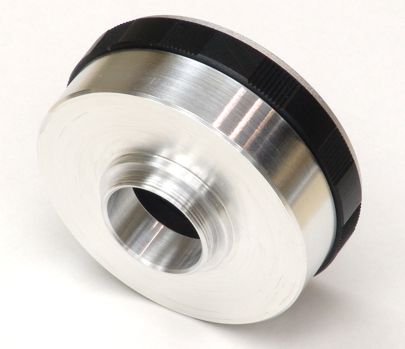 These photos show my design for an EOS lens to C-mount adapter.
This adapter converts any Canon EOS camera lens into a C-mount lens.
This adapts the Canon EF lens mount to C-mount while maintaining parfocality and infinity focus.
The adapter consists of two parts; one is the EF body mount (bayonet receptacle) and the other is the male threaded C-mount fitting.
These photos show my design for an EOS lens to C-mount adapter.
This adapter converts any Canon EOS camera lens into a C-mount lens.
This adapts the Canon EF lens mount to C-mount while maintaining parfocality and infinity focus.
The adapter consists of two parts; one is the EF body mount (bayonet receptacle) and the other is the male threaded C-mount fitting.
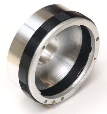
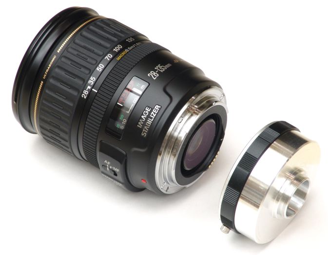 Here we see how the adapter attaches to a typical high-quality Canon EOS camera lens, the Canon EF 28-135mm f/3.5-5.6 IS USM lens.
Of course the Canon lens must be used with manual focus and aperture settings for the C-mount application.
Here we see how the adapter attaches to a typical high-quality Canon EOS camera lens, the Canon EF 28-135mm f/3.5-5.6 IS USM lens.
Of course the Canon lens must be used with manual focus and aperture settings for the C-mount application.
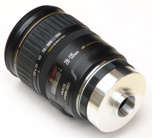 A similar adapter could be made to convert any Nikon F mount or Four-thirds mount lens to C-mount.
Older lens mounts such as Minolta and Pentax K can also be fitted.
Obsolete but high-quality film camera lenses (which are now inexpensive surplus items) can thus be applied to C-mount instrumentation.
A similar adapter could be made to convert any Nikon F mount or Four-thirds mount lens to C-mount.
Older lens mounts such as Minolta and Pentax K can also be fitted.
Obsolete but high-quality film camera lenses (which are now inexpensive surplus items) can thus be applied to C-mount instrumentation.
C-mount to M12x0.5 adapter
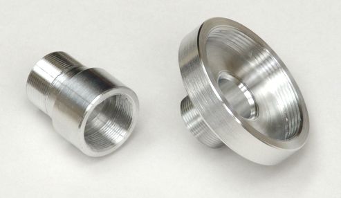 The adapter on the right converts a C-mount lens, such as a video camera lens, to an M12x0.5 thread,
such as is commonly used on webcams and CCD imaging devices .
On the left is an M12x0.5 extension tube.
The adapter on the right converts a C-mount lens, such as a video camera lens, to an M12x0.5 thread,
such as is commonly used on webcams and CCD imaging devices .
On the left is an M12x0.5 extension tube.
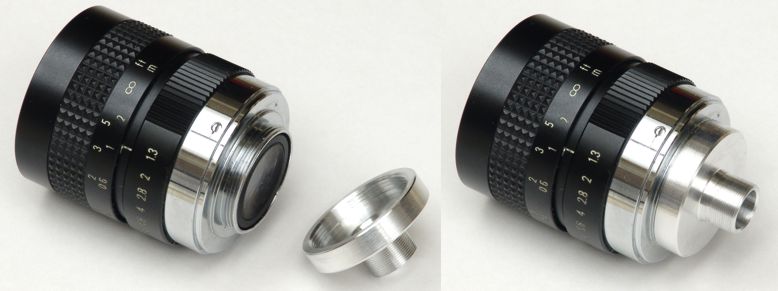 Here is the adapter shown with a small C-mount video camera lens. We design the adapter to place
the focal plane of the lens 3mm past the end of the M12x0.5 threaded tube, which makes it parfocal
with many small-format video assemblies.
The M12x0.5 extension tube with this lens would act as a macro extension tube, allowing very close
focusing and macro magnification.
Here is the adapter shown with a small C-mount video camera lens. We design the adapter to place
the focal plane of the lens 3mm past the end of the M12x0.5 threaded tube, which makes it parfocal
with many small-format video assemblies.
The M12x0.5 extension tube with this lens would act as a macro extension tube, allowing very close
focusing and macro magnification.
Leitz microscope objective thread adapter, M30x0.75 to RMS
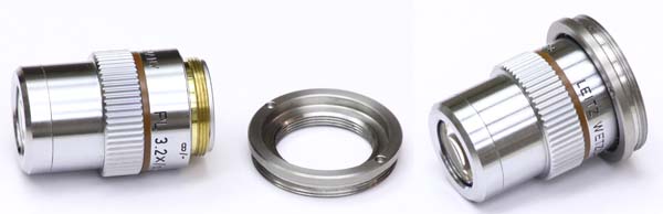 The threaded ring in the center of this photo adapts a Leitz microscope objective with an RMS thread (Royal Microscopy Society standard
0.800"-36 Whitworth thread) to a larger Leitz microscope turret thread which is M30x0.75.
The objective alone is on the left, and shown assembled with the adapter ring on the right.
A recess in the adapter positions the shoulder of the adapted objective at the shoulder of the larger adapted thread.
Spanner holes permit removal of the part with a spanner wrench when tightened into a turret.
Material was 303 stainless steel.
The threaded ring in the center of this photo adapts a Leitz microscope objective with an RMS thread (Royal Microscopy Society standard
0.800"-36 Whitworth thread) to a larger Leitz microscope turret thread which is M30x0.75.
The objective alone is on the left, and shown assembled with the adapter ring on the right.
A recess in the adapter positions the shoulder of the adapted objective at the shoulder of the larger adapted thread.
Spanner holes permit removal of the part with a spanner wrench when tightened into a turret.
Material was 303 stainless steel.
C-mount to ISO 23mm eyepiece adapter:
This drawing [220KB PDF file, 1 page]
shows an adapter that mounts any standard 23.2mm eyepiece on a C-mount lens or microscope photoport.
This also allows inexpensive USB eyepiece video cameras to be used on C-mount instruments,
since those cameras typically supply a standard 23.2mm outside diameter barrel.
The adapter is parfocal, that is, the adapter puts the standard C-mount focal plane at
the same distance as the ISO standard 23.2mm eyepiece focal plane. The length of the eyepiece
barrel projection from its shoulder should be 23.5mm or less to allow insertion to the parfocal distance.
Eyepieces with longer barrels can be used (many are 25mm long) but will require adjusting the focus of the instrument slightly,
or the barrel can be cut or filed down to the shorter length.
EF to M42x1 adapter
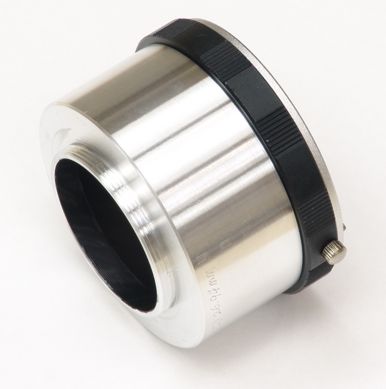 These photos show my design for an EOS lens to M42x1 metric threaded adapter.
This thread is specific to the Pantera Dalsa 1M60 digital instrumentation camera.
This adapts the Canon EF lens mount with its 44mm flange distance to the M42x1 thread
mount while maintaining parfocality and infinity focus for the Dalsa camera's 6.56mm flange distance.
The adapter consists of two parts; one is the EF body mount (bayonet receptacle) and the other is the male threaded M42x1 fitting.
These photos show my design for an EOS lens to M42x1 metric threaded adapter.
This thread is specific to the Pantera Dalsa 1M60 digital instrumentation camera.
This adapts the Canon EF lens mount with its 44mm flange distance to the M42x1 thread
mount while maintaining parfocality and infinity focus for the Dalsa camera's 6.56mm flange distance.
The adapter consists of two parts; one is the EF body mount (bayonet receptacle) and the other is the male threaded M42x1 fitting.
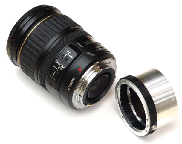 Here we see how the adapter attaches to a typical high-quality Canon EOS camera lens, the Canon EF 28-135mm f/3.5-5.6 IS USM lens.
Of course the Canon lens must be used with manual focus and aperture settings for the Dalsa camera application.
Here we see how the adapter attaches to a typical high-quality Canon EOS camera lens, the Canon EF 28-135mm f/3.5-5.6 IS USM lens.
Of course the Canon lens must be used with manual focus and aperture settings for the Dalsa camera application.
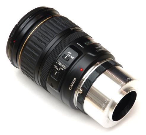
Understanding Standard Filter Threads and Adapters
Filter thread sizes are important to microscope adapters, because it is often much cheaper to make
a custom adapter with a larger thread size than the camera provides.
This is due to the difficulty of machining precision threads up to a shoulder, versus machining threads on the outside of a cylinder without
a shoulder. The larger cylindrical adapter can then be adapted in turn
to the camera's smaller thread size by using an inexpensive, off-the-shelf step-up ring.
Filter threads are not standardized (other than holding to a metric form of arbitrary nominal size),
but over the years camera manufacturers have come to mostly use a standard set of certain whole-millimeter sizes.
While it would have been economical to have a thread series such as is standardized for bolts, the
industry never came to any agreement over this issue, and consequently adapting filter threads from one
size to another is not always possible without a custom-machined item.
The most commonly used filter threads are the 0.75mm pitch of the diameters in the following table.
You are most likely to find inexpensive off-the-shelf step-up and step-down rings which directly or in combination adapt these sizes.
In other words, you can make an inexpensive adapter from any one of these sizes to any of the others,
usually in one step or two steps.
| Common camera filter thread sizes. Inexpensive adapters widely available. |
| 25mm |
27mm |
28mm |
30mm |
34mm |
37mm |
43mm |
46mm |
49mm |
52mm |
55mm |
58mm |
62mm |
67mm |
72mm |
77mm |
82mm |
86mm |
95mm |
Of the above sizes, 37mm is very common on consumer video camera lenses, and 58mm is very common on SLR camera lenses.
The following are less common sizes for you which you may find an off-the-shelf step-up or step-down ring
to one of the above sizes, from which you can get to any other common size, in one or two more steps.
| Not-so-common camera filter thread sizes. Adapters hard-to-find and/or expensive. |
| 25.5mm |
30.5mm |
32.5mm |
32mm |
36mm |
39mm |
40.5mm |
44mm |
48mm |
54mm |
60mm |
If you have to fit a size not listed above, chances are you will not easily find an inexpensive adapter.
Since inserting a ring adds a few millimeters of axial length to the optical system, a single ring or combination of these rings
may insert more than an acceptable length to the adapter. In this case there is no option but to eliminate the step rings by
fabricating the target thread directly on the custom adapter, even though this may amount to an added cost.
If for some reason you need to add length to a filter-thread system, there are also extension rings sold, which are
essentially no-change step-up rings (equal size male and female threads), and which add a typical 5mm to the length.
You can also mate a step-up and step-down ring to make a filter-thread extension ring.
Yet another trick to make an extension ring is to remove the glass from an ordinary photographic filter or close-up lens,
since the filter will have a male and female thread of the same size; on a good-quality filter this is a reversible
modification accomplished with an optical spanner-wrench tool on a threaded ring.
Old filters and close-up lenses are also a source of outside-threaded rings in standard filter thread sizes for making optical assemblies.
Note that the T-mount thread (42mm) and C-mount thread (1"-32tpi) are not to be found in
either of the above series. Since these two threads are intended for camera
lens mounts (mounting the exit end of a lens to a camera) instead of
camera lens filters (mounting a filter on the entrance end of the lens),
off-the-shelf adapters for them adapt things like camera bayonet rings, not
filter threads.
Telescope eyepieces of 1.25 inch OD barrel size typically provide an internal thread
on the object end of M28.5x0.6 for inserting filters (based on my measurements of typical specimens
and the experiences of others; I don't know of a formal standard for this thread).
Telescope eyepieces of 2 inch OD barrel size typically provide an M48x0.75 internal
thread for inserting filters.
Photographic enlarger lenses use several standard threads for mounting. The most common
is the M39x26tpi Leica thread (which is unusual in having an inch pitch on a metric diameter,
perhaps due to use of English lathes in Leica's postwar German manufacturing).
Another major manufacturer of enlarger lenses, Schneider-Kreuznach, uses threads such as
M43x0.75, M35x0.5, M32.5x0.5 (which they call #0), M30x0.5, M28x0.5, M25x0.5 (#00).
I make adapters for all these threads so that enlarger lenses, which are a ready source of highly corrected
lens assemblies of a certain size, may be incorporated into optical systems.
Depth of Field Adapters
 This diagram shows my design for prototyping depth-of-field (DOF) adapter designs. The cage is designed to hold
a cinematic camera lens on the front, a video camera (with its own macro lens) on the rear, and a ground-glass
or light-shaping diffuser inside the cage. The cage consists of two plates held precisely and rigidly
parallel and concentric to each other by threaded rods and nuts.
The center hole of the plates is threaded for M58x0.75 for standard lens adapter hardware, such as the
inexpensive stock male-male macro reversal rings.
The plates are about 5 inches square.
This diagram shows my design for prototyping depth-of-field (DOF) adapter designs. The cage is designed to hold
a cinematic camera lens on the front, a video camera (with its own macro lens) on the rear, and a ground-glass
or light-shaping diffuser inside the cage. The cage consists of two plates held precisely and rigidly
parallel and concentric to each other by threaded rods and nuts.
The center hole of the plates is threaded for M58x0.75 for standard lens adapter hardware, such as the
inexpensive stock male-male macro reversal rings.
The plates are about 5 inches square.
An alternative to the threaded rods is to
use 1/2 inch or 10mm rods (used in cinematic camera systems) in matching through-holes in the plates,
with lock screws into the edges of the plates to fasten the rods.
Instead of lock screws, one end of the rods can be male-threaded and shouldered,
and inserted into the rear plate, which is similarly female threaded.
The area between the plates provides room to insert DOF intermediate imaging devices of the user's choice.
Intermediate plates may be added for this purpose, or the devices may be attached to the rods directly.
A black paper cover, or dark stretchy "sock", covers the cage for light exclusion during exposure.
This "socking" permits the intermediate plane imager to extend outside the boundaries of the case,
allowing for larger components that increase performance or decrease cost.
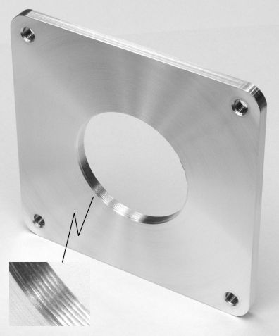 This photo shows an actual DOF cage plate as fabricated.
Photo Eyepieces for Large Cameras
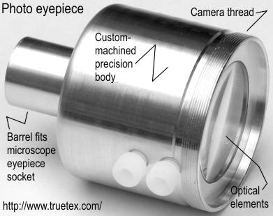 The best-quality digital cameras tend to have large lenses, such as the Canon EOS series of digital SLRs.
Attempting afocal photomicrography through a normal eyepiece necessarily imposes unacceptable vignetting on such
cameras. The solution is to replace the normal eyepiece with a "photo eyepiece", which is a larger eyepiece
designed to examine the same virtual image produced by the microscope objective as the normal eyepiece,
but with apertures and focal lengths consistent
with the entrance pupils of large camera lenses. This is several times more expensive than a simple afocal
adapter, since the mechanical body is many times larger than the afocal adapter, and furthermore,
sophisticated optical elements are required.
The best-quality digital cameras tend to have large lenses, such as the Canon EOS series of digital SLRs.
Attempting afocal photomicrography through a normal eyepiece necessarily imposes unacceptable vignetting on such
cameras. The solution is to replace the normal eyepiece with a "photo eyepiece", which is a larger eyepiece
designed to examine the same virtual image produced by the microscope objective as the normal eyepiece,
but with apertures and focal lengths consistent
with the entrance pupils of large camera lenses. This is several times more expensive than a simple afocal
adapter, since the mechanical body is many times larger than the afocal adapter, and furthermore,
sophisticated optical elements are required.
The photo at the left shows a typical photo eyepiece (mechanical drawing [256KB PDF file])
which I designed and fabricated to adapt a 58mm camera thread to a 23mm eyepiece tube.
This will couple many digital SLRs (such as the Canon EOS series) to the most common
eyepiece standard. The optics are a 4-element symmetric (Plossl) design optimized for microscopy.
This prototyping-styled design provides thumbscrew locks for the optical components,
which allows you to evaluate various optical designs by easily switching various lens elements.
The production version of the design (version 2 below) uses coupled tubes and a spacing ring instead of thumbscrews.
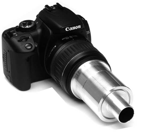 This photo shows version 2 of the photo eyepiece for SLR cameras.
The assembly is shown mounted on a Canon 400D (Canon Digital Rebel XTi) SLR camera, using the
stock 18-55mm Canon lens that is usually bundled with this camera in retail stores.
The photo eyepiece also works with other SLR makes such as Nikon.
This photo shows version 2 of the photo eyepiece for SLR cameras.
The assembly is shown mounted on a Canon 400D (Canon Digital Rebel XTi) SLR camera, using the
stock 18-55mm Canon lens that is usually bundled with this camera in retail stores.
The photo eyepiece also works with other SLR makes such as Nikon.
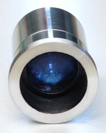 This view into the eyelens end of the photo eyepiece shows the large aperture and short focal length needed to properly
couple the microscope image field to the large camera lens with a proper crop ratio and without vignetting.
This view into the eyelens end of the photo eyepiece shows the large aperture and short focal length needed to properly
couple the microscope image field to the large camera lens with a proper crop ratio and without vignetting.
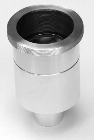 This side view of the assembly shows the mechanical arrangement of the two halves of the eyepiece.
The top half is threaded to mate with the camera lens, possibly with a step-down ring if the lens filter thread is
larger than the most common size of 58mm.
The bottom half is sized to insert into a DIN-standard 23.2mm microscope eyepiece tube;
another version (not shown) fits 30mm standard eyepiece tubes.
This side view of the assembly shows the mechanical arrangement of the two halves of the eyepiece.
The top half is threaded to mate with the camera lens, possibly with a step-down ring if the lens filter thread is
larger than the most common size of 58mm.
The bottom half is sized to insert into a DIN-standard 23.2mm microscope eyepiece tube;
another version (not shown) fits 30mm standard eyepiece tubes.
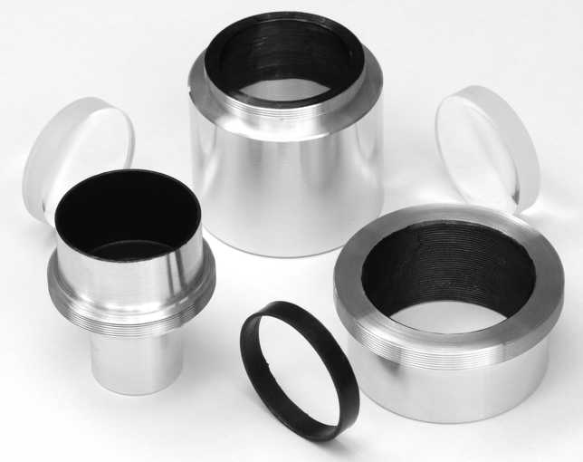 This view shows the assortment of custom components that make up the photo eyepiece assembly.
The aperture and power of the optical elements are calculated to present an infinity view of the microscopic
field in the field-of-view angle acceptable to the camera (which determines the crop ratio), and at an exit pupil which reaches into the
entrance pupil of the camera lens (which eliminates vignetting).
Fully-coated, achromatic elements are used to maximize image contrast and quality.
This view shows the assortment of custom components that make up the photo eyepiece assembly.
The aperture and power of the optical elements are calculated to present an infinity view of the microscopic
field in the field-of-view angle acceptable to the camera (which determines the crop ratio), and at an exit pupil which reaches into the
entrance pupil of the camera lens (which eliminates vignetting).
Fully-coated, achromatic elements are used to maximize image contrast and quality.
 This drawing
[768 KB PDF file] shows the mechanical specifications and features for
the photo eyepiece. The design uses a T-mount intermediate so that it is readily adapted
to other instruments or cameras that require an afocal image with a high exit pupil and narrow apparent field.
This drawing
[768 KB PDF file] shows the mechanical specifications and features for
the photo eyepiece. The design uses a T-mount intermediate so that it is readily adapted
to other instruments or cameras that require an afocal image with a high exit pupil and narrow apparent field.
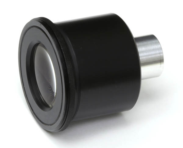 This is version 3 (V3) of the photo eyepiece.
The optional machined Delrin body provides lighter weight with a black interior, instead of the aluminum body with coated interior.
The design reduces the mechanical parts count to 5 custom precision pieces, which contain 4 optical elements in 2 groups.
This item can be ordered directly from me online here.
This is version 3 (V3) of the photo eyepiece.
The optional machined Delrin body provides lighter weight with a black interior, instead of the aluminum body with coated interior.
The design reduces the mechanical parts count to 5 custom precision pieces, which contain 4 optical elements in 2 groups.
This item can be ordered directly from me online here.
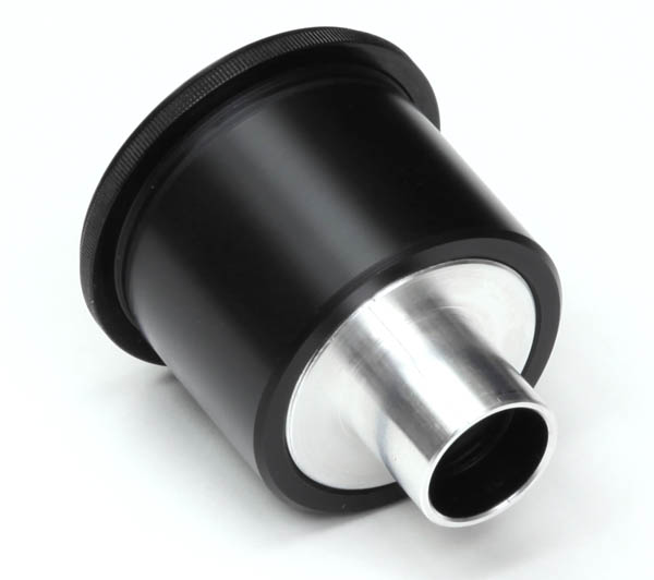 Photo eyepiece V3 showing the eyetube end.
This item is shown as configured for 23.2mm ISO standard eyetubes.
Other options replace the one bottom part to configure for 30mm standard eyetubes, C-mount, ISO 38mm, and Zeiss or Burton slit lamp.
Photo eyepiece V3 showing the eyetube end.
This item is shown as configured for 23.2mm ISO standard eyetubes.
Other options replace the one bottom part to configure for 30mm standard eyetubes, C-mount, ISO 38mm, and Zeiss or Burton slit lamp.
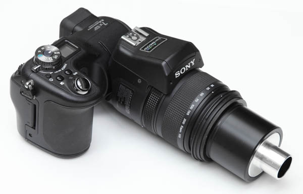 Photo eyepiece V3 shown with Sony DSC-F828 digital camera. This camera model provides a Zeiss zoom lens and the unusual
ability to photograph in
the infrared (Sony "Nightshot") via an internally switched filter. Digital cameras otherwise have a fixed infrared-blocking filter and
are unable to photograph in infrared.
Photo eyepiece V3 shown with Sony DSC-F828 digital camera. This camera model provides a Zeiss zoom lens and the unusual
ability to photograph in
the infrared (Sony "Nightshot") via an internally switched filter. Digital cameras otherwise have a fixed infrared-blocking filter and
are unable to photograph in infrared.
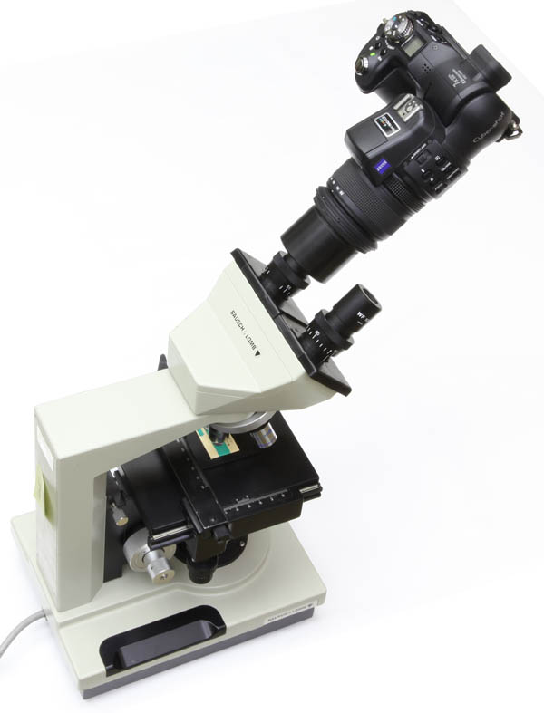 Photo eyepiece V3 with Sony DSC-F828 and Bausch & Lomb Galen II microscope.
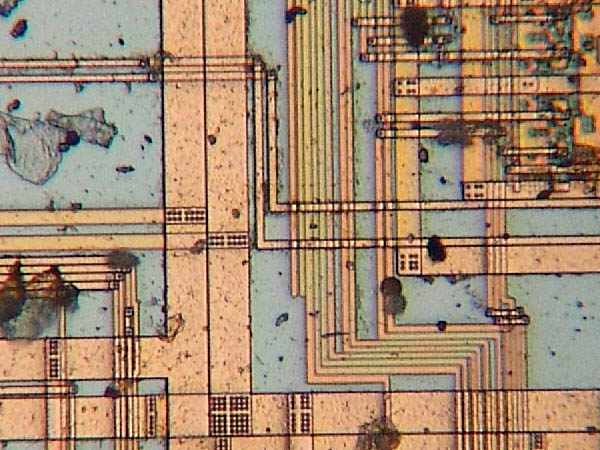 Photo eyepiece V3 sample image: Leitz Orthoplan 0.3mm field width at 200X, 0.5 micron/pixel, showing
a section of an Intel CPU integrated circuit.
Compare to Orthoplan 40X objective with incident-light on a 2 megapixel USB webcam which I refitted for a C-mount adapter and
the Leitz ISO 38mm phototube, yielding images such as this photo showing dried erythrocytes about 6 microns
in diameter.
Photo eyepiece V3 sample image: Leitz Orthoplan 0.3mm field width at 200X, 0.5 micron/pixel, showing
a section of an Intel CPU integrated circuit.
Compare to Orthoplan 40X objective with incident-light on a 2 megapixel USB webcam which I refitted for a C-mount adapter and
the Leitz ISO 38mm phototube, yielding images such as this photo showing dried erythrocytes about 6 microns
in diameter.
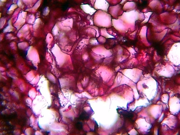 Photo eyepiece V3 sample image: Bausch & Lomb Galen II, 0.54mm field width at 100X, 0.9 micron/pixel, showing
a thin central section of a woody pine stem.
Photo eyepiece V3 sample image: Bausch & Lomb Galen II, 0.54mm field width at 100X, 0.9 micron/pixel, showing
a thin central section of a woody pine stem.
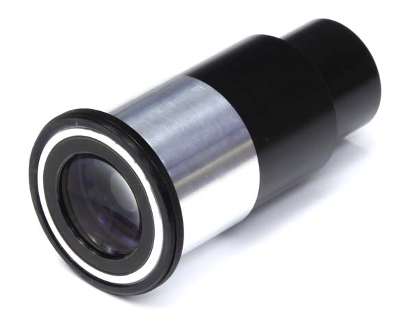 This is the photo eyepiece V3 configured for ISO 38mm phototubes such as are found on Nikon, Leitz, Leica, and Wild microscopes.
This is a larger piece with lots of glass.
The far end in this photo is 38mm in diameter to fit the phototube, and the near end is stepped up to a 58mm diameter filter thread.
This is the photo eyepiece V3 configured for ISO 38mm phototubes such as are found on Nikon, Leitz, Leica, and Wild microscopes.
This is a larger piece with lots of glass.
The far end in this photo is 38mm in diameter to fit the phototube, and the near end is stepped up to a 58mm diameter filter thread.
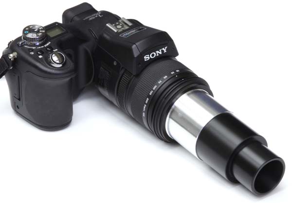 Here is the ISO 38mm photo eyepiece attached to a Sony DSC-F828 digital camera.
This digital camera microscope adapter also works well with other large-lensed cameras such as the Canon G11.
The lenses on these larger digital cameras have entrance pupils deep inside the lens, which can only be reached by a specially designed afocal
adapter with a very long exit pupil (typically 24mm). Trying to shoot photos through an ordinary eyepiece with a typical 13mm eye relief or less will
unavoidably result in severe vignetting.
Here is the ISO 38mm photo eyepiece attached to a Sony DSC-F828 digital camera.
This digital camera microscope adapter also works well with other large-lensed cameras such as the Canon G11.
The lenses on these larger digital cameras have entrance pupils deep inside the lens, which can only be reached by a specially designed afocal
adapter with a very long exit pupil (typically 24mm). Trying to shoot photos through an ordinary eyepiece with a typical 13mm eye relief or less will
unavoidably result in severe vignetting.
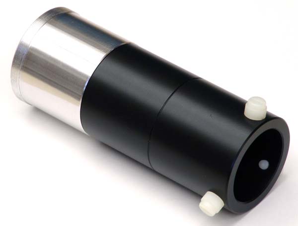 This is the photo eyepiece V3 configured for the Mitutoyo FS70 microscope 38mm photoport dovetail.
The threaded end on the left attaches to the digital camera.
The receptacle on the right end attaches with thumbscrews to the Mitutoyo dovetail fitting.
This is the photo eyepiece V3 configured for the Mitutoyo FS70 microscope 38mm photoport dovetail.
The threaded end on the left attaches to the digital camera.
The receptacle on the right end attaches with thumbscrews to the Mitutoyo dovetail fitting.
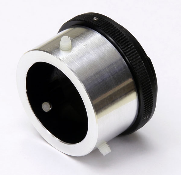 This T-mount adapter allows use of digital SLR camera bodies on the Mitutoyo FS70 microscope 38mm photoport dovetail.
![Olympus Vanox-T AH2 microscope with original 35mm film camera [Armstrong]](ah2c.jpg) The Olympus Vanox-T AH2 research microscope is a
very large and costly instrument from the 1980s which can be upgraded to digital SLR photography with an adapter.
As shown in this photo, the original configuration included ports on the left and right sides of the instrument for 35mm film cameras, and a port on top
for a Polaroid camera.
Photo courtesy of University of Mississippi Medical Center (Bill Armstrong).
The Olympus Vanox-T AH2 research microscope is a
very large and costly instrument from the 1980s which can be upgraded to digital SLR photography with an adapter.
As shown in this photo, the original configuration included ports on the left and right sides of the instrument for 35mm film cameras, and a port on top
for a Polaroid camera.
Photo courtesy of University of Mississippi Medical Center (Bill Armstrong).
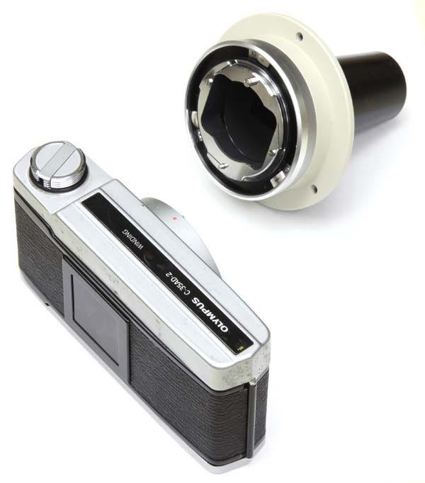 This is a close-up of the original fitting and 35mm film camera body (Olympus C-35AD-2) for an Olympus Vanox-T AH2 research microscope.
This fitting attaches to the main instrument with three screws and is easily removed.
The bayonet design and focal plane location for the old film camera are not standard; they were made specifically for the instrument
and do not fit the Olympus OM or other standard film cameras of the day.
The Olympus C-35AD-2 film camera was specifically made for instrumentation use only, and was much simpler
than a conventional 35mm film camera, lacking features such as a viewfinder or exposure control mechanisms.
Not only was this special film camera body rare, it also provided a very shallow flange distance,
such that a simple bayonet adapter for digital SLR camera mounts (which have longer flange distances) is not physically feasible.
Thus the fitting itself must be shortened and modified in order to fit a digital SLR.
This is a close-up of the original fitting and 35mm film camera body (Olympus C-35AD-2) for an Olympus Vanox-T AH2 research microscope.
This fitting attaches to the main instrument with three screws and is easily removed.
The bayonet design and focal plane location for the old film camera are not standard; they were made specifically for the instrument
and do not fit the Olympus OM or other standard film cameras of the day.
The Olympus C-35AD-2 film camera was specifically made for instrumentation use only, and was much simpler
than a conventional 35mm film camera, lacking features such as a viewfinder or exposure control mechanisms.
Not only was this special film camera body rare, it also provided a very shallow flange distance,
such that a simple bayonet adapter for digital SLR camera mounts (which have longer flange distances) is not physically feasible.
Thus the fitting itself must be shortened and modified in order to fit a digital SLR.
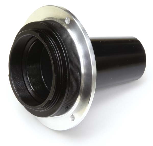 This is my custom adapter which replaces the original Olympus fitting with a T-mount camera thread, which is then adapted for use
with digital SLR cameras.
The adapter is designed to precisely maintain parfocality while fitting directly to the unmodified original hardware.
Attached to the aluminum fitting in the middle is a Canon EF bayonet adapter on the left, and the glare cone from the original film camera fitting.
Installation simply requires unscrewing the old fitting from the instrument, transferring the glare cone to the new adapter, and attaching the assembly
to the main instrument with the original screws.
One may then simply attach a digital SLR camera body to the bayonet to take photos.
This adapter is a larger size than usual on microscopes, having a diameter over 3 inches, but then the Olympus AH2 was a magnificently large
instrument itself.
This is my custom adapter which replaces the original Olympus fitting with a T-mount camera thread, which is then adapted for use
with digital SLR cameras.
The adapter is designed to precisely maintain parfocality while fitting directly to the unmodified original hardware.
Attached to the aluminum fitting in the middle is a Canon EF bayonet adapter on the left, and the glare cone from the original film camera fitting.
Installation simply requires unscrewing the old fitting from the instrument, transferring the glare cone to the new adapter, and attaching the assembly
to the main instrument with the original screws.
One may then simply attach a digital SLR camera body to the bayonet to take photos.
This adapter is a larger size than usual on microscopes, having a diameter over 3 inches, but then the Olympus AH2 was a magnificently large
instrument itself.
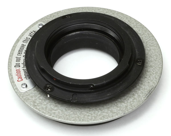 The camera attachment to the Olympus PME metallograph microscope is similar to the Olympus Vanox-T, requiring a modification to the
original film camera attachment to fit Canon digital SLRs.
The photo at left shows the result of my digital upgrade.
The original fitting worked with an Olympus C-35AD-4 35mm film camera.
This fitting attached to the instrument with a dovetail fitting (on the rear side not visible in the photo), which in turn
locked on with thumbscrews for easy removal.
The camera attachment to the Olympus PME metallograph microscope is similar to the Olympus Vanox-T, requiring a modification to the
original film camera attachment to fit Canon digital SLRs.
The photo at left shows the result of my digital upgrade.
The original fitting worked with an Olympus C-35AD-4 35mm film camera.
This fitting attached to the instrument with a dovetail fitting (on the rear side not visible in the photo), which in turn
locked on with thumbscrews for easy removal.
 This drawing
[623 KB PDF file, 1 page] shows an adapter which converts a Tektronix oscilloscope Polaroid camera hood (model XG) to use a digital camera.
This hood constituted the front attachment for the Tektronix C-7 CRT camera auto-film system.
The digital adaptation uses the existing tapered and hinged hood from the old assembly, but replaces the Polaroid camera with a custom converter plate and custom threaded ring to attach a stock conversion lens
adapter for a Canon A-series digital camera. By using the slowest ISO speed setting, macro focus, and wide-angle zoom, the digital camera takes a well-framed
high-resolution photo of the oscilloscope screen, as shown in this sample oscilloscope screen shot
taken from an ophthalmic ultrasound instrument.
This drawing
[623 KB PDF file, 1 page] shows an adapter which converts a Tektronix oscilloscope Polaroid camera hood (model XG) to use a digital camera.
This hood constituted the front attachment for the Tektronix C-7 CRT camera auto-film system.
The digital adaptation uses the existing tapered and hinged hood from the old assembly, but replaces the Polaroid camera with a custom converter plate and custom threaded ring to attach a stock conversion lens
adapter for a Canon A-series digital camera. By using the slowest ISO speed setting, macro focus, and wide-angle zoom, the digital camera takes a well-framed
high-resolution photo of the oscilloscope screen, as shown in this sample oscilloscope screen shot
taken from an ophthalmic ultrasound instrument.
 This drawing
[408 KB PDF file, 1 page] and the following photo
show an adapter which adapts a digital camera to an American Optical (AO) microscope model 10, 110 or 120, or Reichert Microstar microscope,
using the trinocular port. An 23mm eyepiece adapter also works on these microscopes when not equipped with a photoport.
This drawing
[408 KB PDF file, 1 page] and the following photo
show an adapter which adapts a digital camera to an American Optical (AO) microscope model 10, 110 or 120, or Reichert Microstar microscope,
using the trinocular port. An 23mm eyepiece adapter also works on these microscopes when not equipped with a photoport.
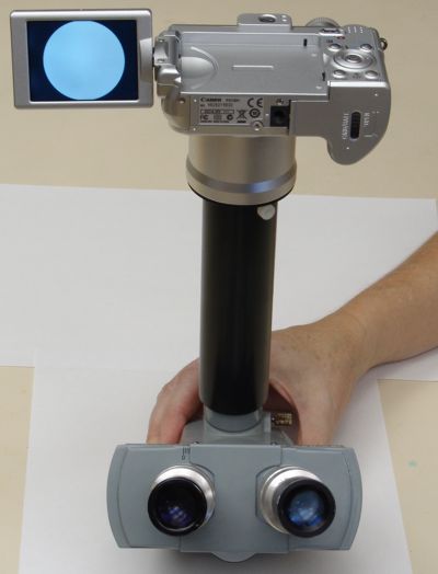
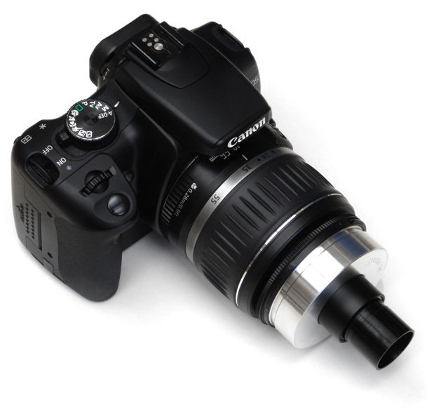 This photo shows my latest design for an digital SLR camera to microscope adapter for 23mm eyetubes using the afocal mode.
This is an afocal design which uses the stock 18-55mm lens sold as a kit with the Canon Digital Rebel SLRs.
This adapter also works with the similar Nikon 18-55mm kit lens for the Nikon D40, D60, D80, D200 and D300.
The zoom feature of the stock lens allows you to choose the cropping of the circular microscope field of view to the rectangular camera field,
as described below under "Understanding Cropping".
This photo shows my latest design for an digital SLR camera to microscope adapter for 23mm eyetubes using the afocal mode.
This is an afocal design which uses the stock 18-55mm lens sold as a kit with the Canon Digital Rebel SLRs.
This adapter also works with the similar Nikon 18-55mm kit lens for the Nikon D40, D60, D80, D200 and D300.
The zoom feature of the stock lens allows you to choose the cropping of the circular microscope field of view to the rectangular camera field,
as described below under "Understanding Cropping".
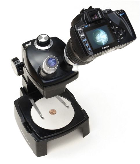 Here is the application of the photo eyepiece to a Bausch and Lomb StereoZoom microscope.
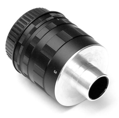 This adapter fits a Bausch and Lomb StereoZoom 7 microscope equipped with a trinocular camera port to a digital SLR camera via an SLR bayonet fitting.
The port receptacle on the microscope is 27mm inner diameter, with two thumbscrews at 90 degrees to clamp onto the adapter tube.
The assembly consists of a custom adapter for the 27mm receptacle, with stock macro extension tubes selected for parfocal projection distance.
These tubes are available for Canon, Nikon, Olympus, and other SLR camera makes.
This adapter fits a Bausch and Lomb StereoZoom 7 microscope equipped with a trinocular camera port to a digital SLR camera via an SLR bayonet fitting.
The port receptacle on the microscope is 27mm inner diameter, with two thumbscrews at 90 degrees to clamp onto the adapter tube.
The assembly consists of a custom adapter for the 27mm receptacle, with stock macro extension tubes selected for parfocal projection distance.
These tubes are available for Canon, Nikon, Olympus, and other SLR camera makes.
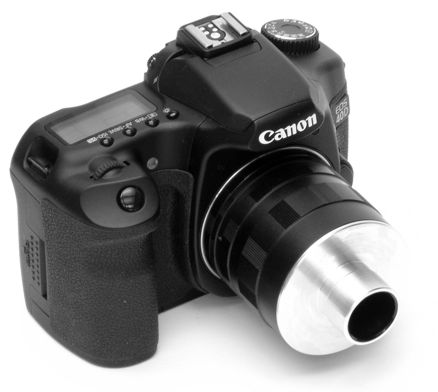 This is the adapter on a Canon 40D digital SLR.
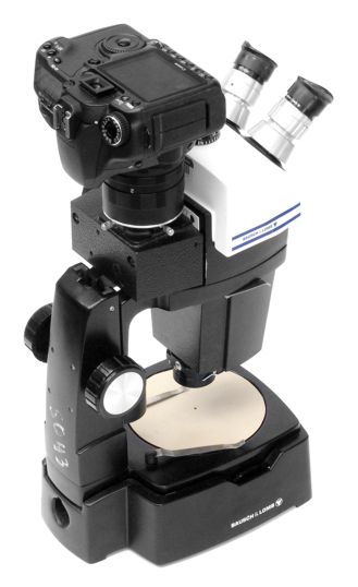 Here is the adapter and digital SLR camera on the Bausch and Lomb trinocular StereoZoom 7.
This configuration provides an inscribed crop, so that photographs cover all of the eyepiece field of view.
Lengthening the adapter tube (by simply stacking additional stock macro extension pieces) projects the image further
and thus with more magnification, tightening the crop. A slight defocusing is then required so the adaptation is
no longer parfocal.
Here is the adapter and digital SLR camera on the Bausch and Lomb trinocular StereoZoom 7.
This configuration provides an inscribed crop, so that photographs cover all of the eyepiece field of view.
Lengthening the adapter tube (by simply stacking additional stock macro extension pieces) projects the image further
and thus with more magnification, tightening the crop. A slight defocusing is then required so the adaptation is
no longer parfocal.
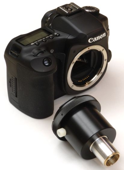 This photo shows my latest design for a digital SLR camera to microscope adapter for 23mm eyetubes using relay lens projection.
The adapter replaces the usual camera lens to couple the microscope to the camera.
This is a more expensive adapter than the afocal type, because it involves more optical elements and mechanical structure.
Having less glass in the optical path, however, the image quality is better than afocal adapters.
The camera side of the adapter is a T-mount standard, meaning it works with Canon, Nikon, and Olympus (Four-Thirds) digital SLRs.
This adapter is also available for C-mount interfaces to digital SLR cameras.
See the instruction sheet for using these adapters.
This photo shows my latest design for a digital SLR camera to microscope adapter for 23mm eyetubes using relay lens projection.
The adapter replaces the usual camera lens to couple the microscope to the camera.
This is a more expensive adapter than the afocal type, because it involves more optical elements and mechanical structure.
Having less glass in the optical path, however, the image quality is better than afocal adapters.
The camera side of the adapter is a T-mount standard, meaning it works with Canon, Nikon, and Olympus (Four-Thirds) digital SLRs.
This adapter is also available for C-mount interfaces to digital SLR cameras.
See the instruction sheet for using these adapters.
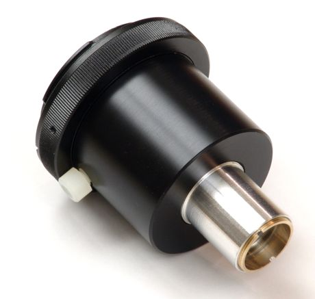 This SLR relay lens adapter can be ordered online here (for USA shipping) or here (for international shipping).
Besides the 23mm version, I also configure it to 30mm, 37mm, or 38mm microscope phototubes or eyetubes,
Zeiss 25mm eyetubes, C-mount, Topcon eyetubes, or Haag-Streit 23.5mm eyetubes, as you request.
This SLR relay lens adapter can be ordered online here (for USA shipping) or here (for international shipping).
Besides the 23mm version, I also configure it to 30mm, 37mm, or 38mm microscope phototubes or eyetubes,
Zeiss 25mm eyetubes, C-mount, Topcon eyetubes, or Haag-Streit 23.5mm eyetubes, as you request.
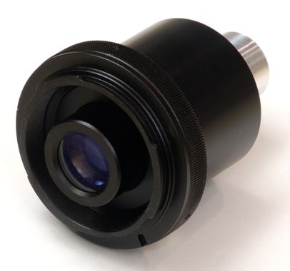
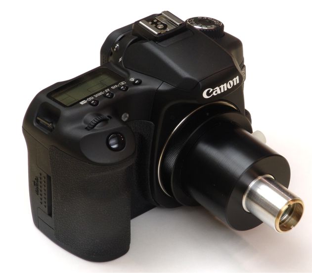
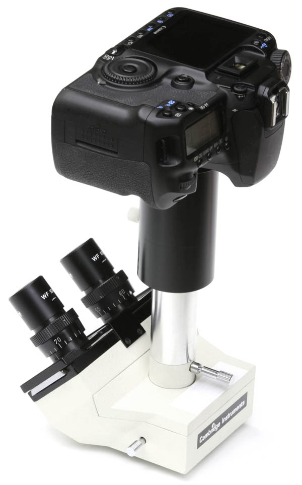 This version of the relay lens SLR adapter provides a 2.5X magnification, which crops the digital image area into the
central portion of the eyepiece field of view. This yields an "outscribed" crop in terms of my cropping conventions,
when applied to a full-frame digital SLR camera such as the Canon 5D Mark II, instead of the less desirable inscribed crop
of a 1X direct-projection adapter.
The adapter here is fitted to the photo port of a Cambridge Instruments trinocular microscope.
The Cambridge brand was involved with Leica, and Bausch and Lomb, at various times in past decades.
Zeiss made a trinocular assembly with a similar 23mm photo port for the venerable Zeiss Standard series of microscopes,
and this type of adapter is suitable for that application as well.
The top end of the adapter is a T-mount fitting, making this adapter configurable for other makes of digital SLRs.
This version of the relay lens SLR adapter provides a 2.5X magnification, which crops the digital image area into the
central portion of the eyepiece field of view. This yields an "outscribed" crop in terms of my cropping conventions,
when applied to a full-frame digital SLR camera such as the Canon 5D Mark II, instead of the less desirable inscribed crop
of a 1X direct-projection adapter.
The adapter here is fitted to the photo port of a Cambridge Instruments trinocular microscope.
The Cambridge brand was involved with Leica, and Bausch and Lomb, at various times in past decades.
Zeiss made a trinocular assembly with a similar 23mm photo port for the venerable Zeiss Standard series of microscopes,
and this type of adapter is suitable for that application as well.
The top end of the adapter is a T-mount fitting, making this adapter configurable for other makes of digital SLRs.
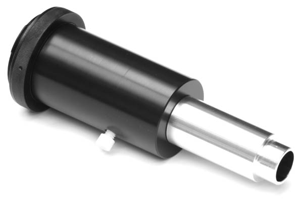
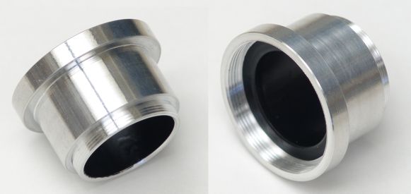 This adapter mounts an Imaging Source camera on a Questar telescope.
The adapter provides an M30x0.75 male thread on one end to couple to the Questar optics.
The other end provides an unusual M36.4x1.0 female thread, which is required to couple to a Borg 7315 helical focuser.
This adapter replaces the Borg 7316 adapter which ordinarily would be used with the Borg 7315 focuser
to obtain a 1.25 inch eyepiece slip fit.
The interior of the adapter is blackened to cut down stray light and improve contrast.
Careful design of the adapter is critical to avoiding mechanical interference with the close arrangement of the
focusing knob and other features on the Questar scope.
This adapter mounts an Imaging Source camera on a Questar telescope.
The adapter provides an M30x0.75 male thread on one end to couple to the Questar optics.
The other end provides an unusual M36.4x1.0 female thread, which is required to couple to a Borg 7315 helical focuser.
This adapter replaces the Borg 7316 adapter which ordinarily would be used with the Borg 7315 focuser
to obtain a 1.25 inch eyepiece slip fit.
The interior of the adapter is blackened to cut down stray light and improve contrast.
Careful design of the adapter is critical to avoiding mechanical interference with the close arrangement of the
focusing knob and other features on the Questar scope.
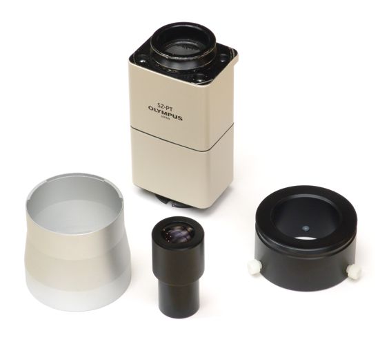 This photo shows an Olympus SZ-PT phototube with the adapter components for a Canon A-series digital camera.
This Olympus phototube mounts on the photo port of Olympus SZ series stereozoom microscopes.
In front of the photo, from left to right, are shown the stock conversion lens adapter tube, the afocal photo eyepiece, and
the custom adapter. The afocal photo eyepiece replaces the Olympus NFK 3.3X LD 125 photo eyepiece (or
Olympus NFK 2.5X LD 125 photo eyepiece) which were used in the Olympus SZ-PT phototube to project an enlarged image
onto a 35mm film frame in a lensless camera back. Instead of a projected image, the new eyepiece presents
an infinity image with proper pupil and field angle for the lensed Canon digital camera to photograph.
This adapter also works with the Canon EF 18-55mm zoom lens on Canon digital SLR cameras, although a focal adapter
of similar size would produce better images by virtue of less glass.
This photo shows an Olympus SZ-PT phototube with the adapter components for a Canon A-series digital camera.
This Olympus phototube mounts on the photo port of Olympus SZ series stereozoom microscopes.
In front of the photo, from left to right, are shown the stock conversion lens adapter tube, the afocal photo eyepiece, and
the custom adapter. The afocal photo eyepiece replaces the Olympus NFK 3.3X LD 125 photo eyepiece (or
Olympus NFK 2.5X LD 125 photo eyepiece) which were used in the Olympus SZ-PT phototube to project an enlarged image
onto a 35mm film frame in a lensless camera back. Instead of a projected image, the new eyepiece presents
an infinity image with proper pupil and field angle for the lensed Canon digital camera to photograph.
This adapter also works with the Canon EF 18-55mm zoom lens on Canon digital SLR cameras, although a focal adapter
of similar size would produce better images by virtue of less glass.
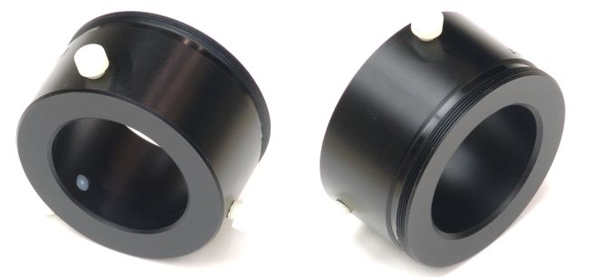 This shows two views of the custom adapter tube. The material is black Delrin, a sturdy engineering polymer which
machines well and requires no further treatment for optical blackening.
Nylon thumbscrews lock the adapter kinematically onto the dovetail fitting of the Olympus SZ-PT phototube.
The adapter provides a standard M58x0.75 filter thread to directly fit the lens tube on the digital camera.
Any thread size down to 37mm can be fabricated on this basic design, which makes it compatible with digital video cameras as well.
This shows two views of the custom adapter tube. The material is black Delrin, a sturdy engineering polymer which
machines well and requires no further treatment for optical blackening.
Nylon thumbscrews lock the adapter kinematically onto the dovetail fitting of the Olympus SZ-PT phototube.
The adapter provides a standard M58x0.75 filter thread to directly fit the lens tube on the digital camera.
Any thread size down to 37mm can be fabricated on this basic design, which makes it compatible with digital video cameras as well.
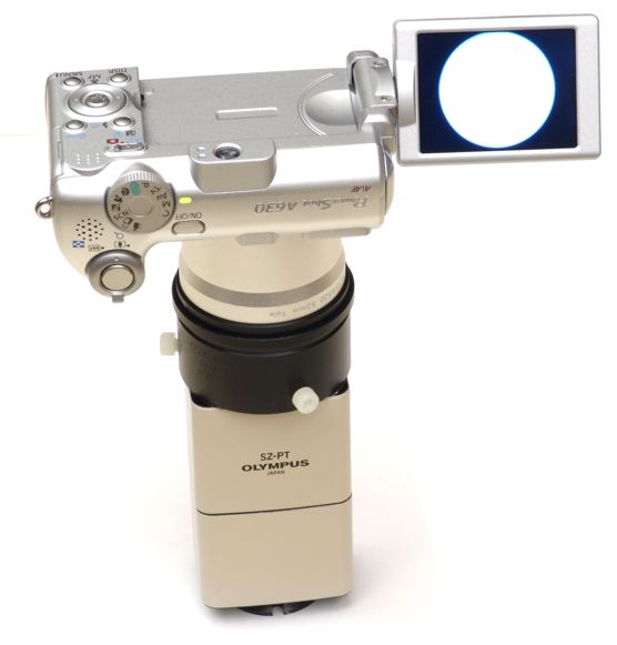 Here is the Olympus SZ-PT adapter assembled with a Canon A630 digital camera, as it would be positioned on top
of the Olympus microscope. The microscope field of view is inscribed-cropped onto the Canon camera field of view.
This model of Canon camera provides an articulated LCD which you can orient for convenient viewing of the trinocular image;
without this feature on the camera, you must lean awkwardly over the top of the instrument to see the LCD.
By positioning top of the camera towards the front of the microscope, you can conveniently reach the shutter button.
The SZ-PT phototube itself can be replaced with this same type of custom adapter in a longer size, since the
Olympus phototube contains only very low power optics to slightly resize the image for the (now unused) NFK photo eyepieces.
Here is the Olympus SZ-PT adapter assembled with a Canon A630 digital camera, as it would be positioned on top
of the Olympus microscope. The microscope field of view is inscribed-cropped onto the Canon camera field of view.
This model of Canon camera provides an articulated LCD which you can orient for convenient viewing of the trinocular image;
without this feature on the camera, you must lean awkwardly over the top of the instrument to see the LCD.
By positioning top of the camera towards the front of the microscope, you can conveniently reach the shutter button.
The SZ-PT phototube itself can be replaced with this same type of custom adapter in a longer size, since the
Olympus phototube contains only very low power optics to slightly resize the image for the (now unused) NFK photo eyepieces.
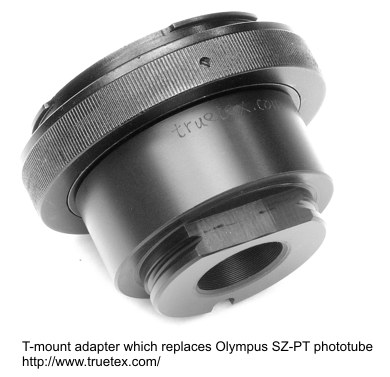 This adapter replaces the Olympus SZ-PT phototube with a T-mount interface.
The adapter is shown here with a Canon EF lens mount.
This allows a digital SLR camera to be mounted directly on the Olympus stereo zoom microscope trinocular photoport.
The optical principle is direct projection onto the camera's sensor, without any relay lens optics, providing the highest-quality images.
Length is chosen to make the digital camera precisely parfocal with the binocular eyepiece view.
This adapter replaces the Olympus SZ-PT phototube with a T-mount interface.
The adapter is shown here with a Canon EF lens mount.
This allows a digital SLR camera to be mounted directly on the Olympus stereo zoom microscope trinocular photoport.
The optical principle is direct projection onto the camera's sensor, without any relay lens optics, providing the highest-quality images.
Length is chosen to make the digital camera precisely parfocal with the binocular eyepiece view.
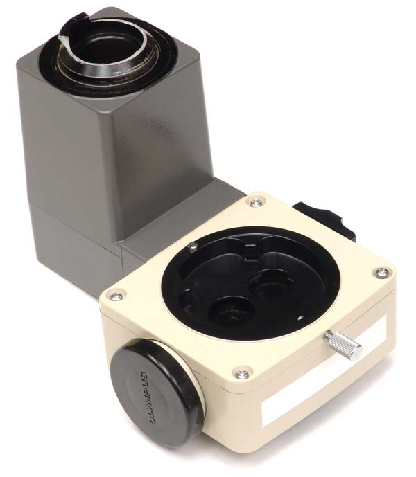 This is a damaged beamsplitter for an Olympus SZH stereo microscope.
The dovetail fitting, seen at the top of the square pillar, has been broken off at its weakest point due to the old camera attachment being bumped,
perhaps with the thumbscrews overtightened and stressing the metal.
Without this attachment, this fine instrument is unable to take photographs and loses much of its value.
This beamsplitter was a rare option which is no longer made, and very costly to replace today, if it can be found at all.
The unfortunate owner contacted me about a unique repair fabrication, which I agreed to attempt.
This is a damaged beamsplitter for an Olympus SZH stereo microscope.
The dovetail fitting, seen at the top of the square pillar, has been broken off at its weakest point due to the old camera attachment being bumped,
perhaps with the thumbscrews overtightened and stressing the metal.
Without this attachment, this fine instrument is unable to take photographs and loses much of its value.
This beamsplitter was a rare option which is no longer made, and very costly to replace today, if it can be found at all.
The unfortunate owner contacted me about a unique repair fabrication, which I agreed to attempt.
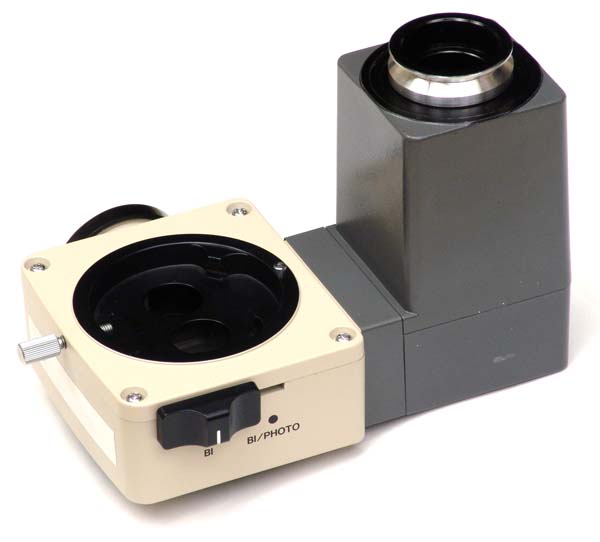 I repaired the fitting by disassembling the square casting from the rest of the beamsplitter and
mounting it in a 4-jaw chuck in the lathe. Through some old-fashioned precision indicator measurements, I carefully adjusted
this piece of work in the chuck jaws to align the optical axis with the lathe axis.
I cut and faced the broken dovetail portion off the casting.
I bored and threaded a hole into the casting, sized to the remaining metal, which would receive a repair fitting.
Cutting the old metal parts like this is risky, because botching any step can ruin the piece beyond repair, and
fabricating a replacement from scratch would be uneconomical.
In this case, the cutting succeeded.
I designed and fabricated a threaded dovetail repair fitting to fit the new threaded hole.
Good as new!
By adding my T-mount adapter tube (see below), the Olympus SZH is ready for high-resolution photography with a standard
digital SLR camera body.
I repaired the fitting by disassembling the square casting from the rest of the beamsplitter and
mounting it in a 4-jaw chuck in the lathe. Through some old-fashioned precision indicator measurements, I carefully adjusted
this piece of work in the chuck jaws to align the optical axis with the lathe axis.
I cut and faced the broken dovetail portion off the casting.
I bored and threaded a hole into the casting, sized to the remaining metal, which would receive a repair fitting.
Cutting the old metal parts like this is risky, because botching any step can ruin the piece beyond repair, and
fabricating a replacement from scratch would be uneconomical.
In this case, the cutting succeeded.
I designed and fabricated a threaded dovetail repair fitting to fit the new threaded hole.
Good as new!
By adding my T-mount adapter tube (see below), the Olympus SZH is ready for high-resolution photography with a standard
digital SLR camera body.
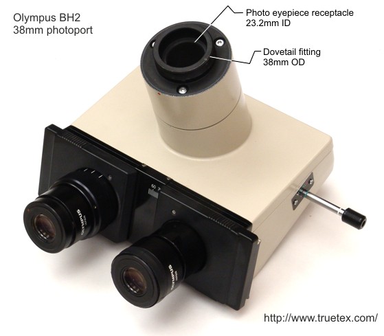 This Olympus BH2 trinocular head provides the Olympus standard 38mm photoport used on many Olympus models.
The BH2 is a conventional compound microscope, instead of the stereo zoom type used with incident
light as shown above with the Olympus SZ-PT fitting.
The exit of the photoport consists of a 38mm outside diameter dovetail fitting, with a recessed receptacle
for a photo eyepiece with 23.2mm barrel.
This 38mm fitting should not be confused with the ISO standard 38mm photoport used by Leica, Leitz, and Nikon, where 38mm is
the inside diameter of the phototube instead of the outside diameter of the fitting in the Olympus usage.
In keeping with the DIN 23.2mm eyetube standard, when the eyepiece view is in focus,
the photoport image plane is focused 10mm inside the shoulder of the phototube registration surface.
This establishes a parfocal calibration of the camera focus to the focused binocular eyepiece view.
This Olympus BH2 trinocular head provides the Olympus standard 38mm photoport used on many Olympus models.
The BH2 is a conventional compound microscope, instead of the stereo zoom type used with incident
light as shown above with the Olympus SZ-PT fitting.
The exit of the photoport consists of a 38mm outside diameter dovetail fitting, with a recessed receptacle
for a photo eyepiece with 23.2mm barrel.
This 38mm fitting should not be confused with the ISO standard 38mm photoport used by Leica, Leitz, and Nikon, where 38mm is
the inside diameter of the phototube instead of the outside diameter of the fitting in the Olympus usage.
In keeping with the DIN 23.2mm eyetube standard, when the eyepiece view is in focus,
the photoport image plane is focused 10mm inside the shoulder of the phototube registration surface.
This establishes a parfocal calibration of the camera focus to the focused binocular eyepiece view.
These microscopes were made in the film camera era, and the photoports were equipped for film photography.
An Olympus photo eyepiece for film photography, such as an "NFK 2.5X LD 125",
is designed not to produce an afocal image such as you would view by eye, but instead to relay an image 125mm further
up from the registration surface, the image being enlarged 2.5 times. This was a common configuration for 35mm film
photography, which provided an outscribed cropping of the microscopic field of view onto the film frame.
The film camera would have been mounted on an extension tube such that the film plane was held 125mm above the dovetail
fitting to establish parfocal operation with the binocular eyepiece view.
The selector rod on the right of the unit switched internal beamsplitter optics to direct the image to the eyepieces only,
the eyepieces and photoport, or the photoport only.
This focal arrangement is not suitable for use with an afocal digital point-and-shoot camera.
So to adapt this port to digital photography, we provide
instead an afocal photo eyepiece with a generously distanced exit pupil that can reach the entrance pupil of a typical digital camera lens.
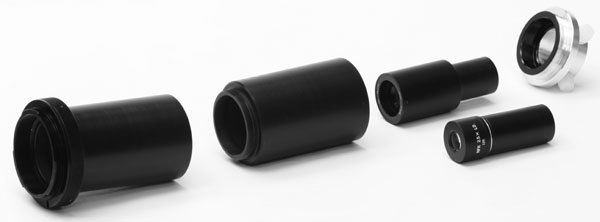 This assembly of custom adapters fits a digital SLR to the Olympus NFK or Nikon CF PL photo projection eyepieces with a T-mount clamp and
T-mount extension tubes onto a microscope's
25mm trinocular tube. This type of 25mm trinocular tube was common to many classic Zeiss, Olympus, Nikon, Leica, Wild-Heerbrugg, etc.,
microscopes until these leading manufacturers diverged into proprietary fittings for attaching cameras in the 1980s.
Many import manufacturers today continue to use this well-standardized and respectable trinocular format instead of difficult-to-fit
proprietary methods.
Shown here are (left to right) a custom 75mm-long T-mount extension tube with stock Canon T-mount adapter,
another bare 75mm T-mount extension tube, two suitable photo projection eyepieces (Olympus NFK 2.5X LD and Nikon CF PL 2.5X),
and a custom clamp for 25mm trinocular tubes.
The "25mm" refers to the outside diameter of the microscope tube, which had a 23.2mm inner diameter which accepted standard
eyepieces. The photo eyepieces, instead of producing an afocal image for inspection by eye like an ordinary eyepiece,
were shifted slightly and corrected to project (that is, relay) a focal image some distance away with some enlargement.
Thus the normal eyetube fitting was adapted optically to project an image onto a 35mm film frame (or now onto a digital camera
sensor) instead of presenting an afocal image for the observer's eye.
This assembly of custom adapters fits a digital SLR to the Olympus NFK or Nikon CF PL photo projection eyepieces with a T-mount clamp and
T-mount extension tubes onto a microscope's
25mm trinocular tube. This type of 25mm trinocular tube was common to many classic Zeiss, Olympus, Nikon, Leica, Wild-Heerbrugg, etc.,
microscopes until these leading manufacturers diverged into proprietary fittings for attaching cameras in the 1980s.
Many import manufacturers today continue to use this well-standardized and respectable trinocular format instead of difficult-to-fit
proprietary methods.
Shown here are (left to right) a custom 75mm-long T-mount extension tube with stock Canon T-mount adapter,
another bare 75mm T-mount extension tube, two suitable photo projection eyepieces (Olympus NFK 2.5X LD and Nikon CF PL 2.5X),
and a custom clamp for 25mm trinocular tubes.
The "25mm" refers to the outside diameter of the microscope tube, which had a 23.2mm inner diameter which accepted standard
eyepieces. The photo eyepieces, instead of producing an afocal image for inspection by eye like an ordinary eyepiece,
were shifted slightly and corrected to project (that is, relay) a focal image some distance away with some enlargement.
Thus the normal eyetube fitting was adapted optically to project an image onto a 35mm film frame (or now onto a digital camera
sensor) instead of presenting an afocal image for the observer's eye.
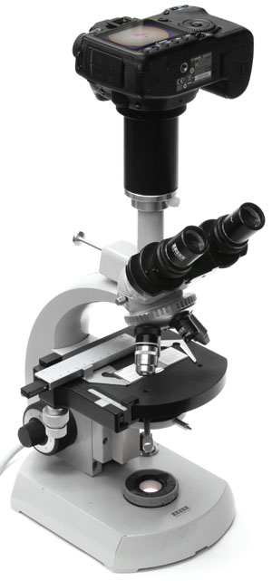 Here is the photo eyepiece adapter clamped on a classic Zeiss Standard microscope from the 1970s, a laboratory instrument which still
performs superbly today.
This microscope could be had with an ordinary binocular or, as shown here, with a trinocular that provided a 25mm outside-diameter
tube for photography. One pushed the plunger (projecting out the back in this view) in or out to switch the image from the
binocular view to the camera trinocular. My clamp design on the bottom of the adapter locks onto the tube through use of
two nylon thumbscrews. This permits adjustment up and down on the trinocular tube which provides a range of enlargements
and parfocality in the camera. Inside the adapter one inserts the Olympus NFK or Nikon CF PL photo projection eyepieces, which
are high-quality optical items readily available used, and available in a variety of magnifications from 1.67X to 5X.
Since the less expensive digital SLR cameras provide a sensor smaller than 35mm film, one generally chooses the rare 1.67X or more easily
found 2.5X magnifications, together with the sliding adjustment, to yield a photo cropping in between inscribed and outscribed.
By simply threading on a second 75mm T-mount extension tube to the stack, one gains more enlargement for a higher photo magnification
and tighter cropping. The Olympus versus Nikon projection eyepieces were predicated on the adapter projection length of
nominally 125mm versus 215mm, so by suitable choice of these two types of photo eyepieces, and by stacking either one or two extension tubes,
one obtains a wide range of magnifications and parfocality.
Here is the photo eyepiece adapter clamped on a classic Zeiss Standard microscope from the 1970s, a laboratory instrument which still
performs superbly today.
This microscope could be had with an ordinary binocular or, as shown here, with a trinocular that provided a 25mm outside-diameter
tube for photography. One pushed the plunger (projecting out the back in this view) in or out to switch the image from the
binocular view to the camera trinocular. My clamp design on the bottom of the adapter locks onto the tube through use of
two nylon thumbscrews. This permits adjustment up and down on the trinocular tube which provides a range of enlargements
and parfocality in the camera. Inside the adapter one inserts the Olympus NFK or Nikon CF PL photo projection eyepieces, which
are high-quality optical items readily available used, and available in a variety of magnifications from 1.67X to 5X.
Since the less expensive digital SLR cameras provide a sensor smaller than 35mm film, one generally chooses the rare 1.67X or more easily
found 2.5X magnifications, together with the sliding adjustment, to yield a photo cropping in between inscribed and outscribed.
By simply threading on a second 75mm T-mount extension tube to the stack, one gains more enlargement for a higher photo magnification
and tighter cropping. The Olympus versus Nikon projection eyepieces were predicated on the adapter projection length of
nominally 125mm versus 215mm, so by suitable choice of these two types of photo eyepieces, and by stacking either one or two extension tubes,
one obtains a wide range of magnifications and parfocality.
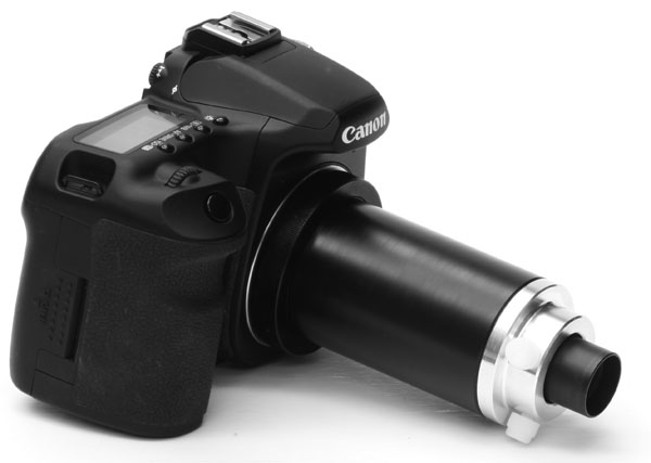 This is the 25mm trinocular adapter on the digital camera and off the microscope. You can see the 23.2mm eyepiece tube projecting from the end of the
adapter. This eyepiece fits into the inner diameter of the microscope's trinocular tube, while the metal clamp and thumbscrews
lock the adapter assembly onto the outside diameter fo the trinocular tube.
This is the 25mm trinocular adapter on the digital camera and off the microscope. You can see the 23.2mm eyepiece tube projecting from the end of the
adapter. This eyepiece fits into the inner diameter of the microscope's trinocular tube, while the metal clamp and thumbscrews
lock the adapter assembly onto the outside diameter fo the trinocular tube.
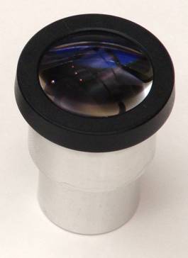 This is my custom photo eyepiece design for 23.2mm phototubes. The 3-element optical cell provides a 20mm field number
while maintaining over 25mm of pupil distance, allowing it to interface with many digital camera lenses with deep pupils.
It is also slimmed down on the outside diameter to fit into the restricted Olympus phototube recess.
This is my custom photo eyepiece design for 23.2mm phototubes. The 3-element optical cell provides a 20mm field number
while maintaining over 25mm of pupil distance, allowing it to interface with many digital camera lenses with deep pupils.
It is also slimmed down on the outside diameter to fit into the restricted Olympus phototube recess.
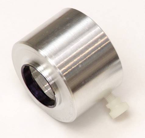 The second part of the Olympus adapter requires a custom standoff mechanism to hold the digital camera at the proper spacing from
the photo eyepiece. This spacing maintains the alignment of the exit pupil of the photo eyepiece
with the entrance pupil of the digital camera, which is the condition to avoid vignetting.
Surface exposed to the light path are blackened to avoid contrast-robbing glare.
The standoff part consists of a sleeve with thumbscrew lock onto the Olympus dovetail, ending in a filter thread to mate to the
camera, all of a length to establish proper pupil spacing.
The standoff adapter is specific to each digital camera model, since each model has a different pupil spacing.
The threaded connection is also specific to each camera, the Nikon 950, 990, 995, 4500, etc., models all use an M28x0.75 thread.
More common is a 52mm (M52x0.75) or 58mm (M58x0.75) conversion lens adapter tube for the Canon A or G models.
Only the sleeve tube needs to be switched to change camera models; the photo eyepiece fits a wide range of models.
This allows inexpensive upgrading of the adapter for new digital cameras as price and performance continue to improve.
The second part of the Olympus adapter requires a custom standoff mechanism to hold the digital camera at the proper spacing from
the photo eyepiece. This spacing maintains the alignment of the exit pupil of the photo eyepiece
with the entrance pupil of the digital camera, which is the condition to avoid vignetting.
Surface exposed to the light path are blackened to avoid contrast-robbing glare.
The standoff part consists of a sleeve with thumbscrew lock onto the Olympus dovetail, ending in a filter thread to mate to the
camera, all of a length to establish proper pupil spacing.
The standoff adapter is specific to each digital camera model, since each model has a different pupil spacing.
The threaded connection is also specific to each camera, the Nikon 950, 990, 995, 4500, etc., models all use an M28x0.75 thread.
More common is a 52mm (M52x0.75) or 58mm (M58x0.75) conversion lens adapter tube for the Canon A or G models.
Only the sleeve tube needs to be switched to change camera models; the photo eyepiece fits a wide range of models.
This allows inexpensive upgrading of the adapter for new digital cameras as price and performance continue to improve.
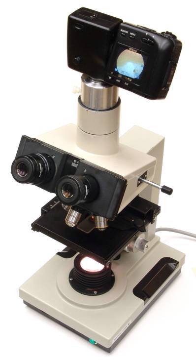 Here is a complete microscope assembly featuring photomicrography using the custom adapter and photo eyepiece with Nikon 950 digital camera.
This Nikon model is now a vintage specimen, having been introduced in 1999, but it was readily
adapted to photomicrography.by virtue of its standard filter thread and moderate 19mm pupil depth in the wide-angle setting.
More suitable today would be a Canon A590 or Canon G11 camera.
Here is a complete microscope assembly featuring photomicrography using the custom adapter and photo eyepiece with Nikon 950 digital camera.
This Nikon model is now a vintage specimen, having been introduced in 1999, but it was readily
adapted to photomicrography.by virtue of its standard filter thread and moderate 19mm pupil depth in the wide-angle setting.
More suitable today would be a Canon A590 or Canon G11 camera.
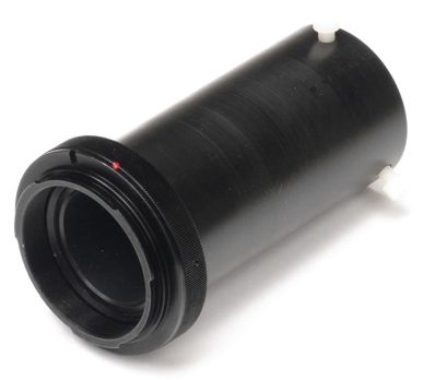 In this photo, we see an adapter for this same Olympus 38mm photoport, but with an extension tube and T-mount fitting for
a digital SLR camera.
In this photo, we see an adapter for this same Olympus 38mm photoport, but with an extension tube and T-mount fitting for
a digital SLR camera.
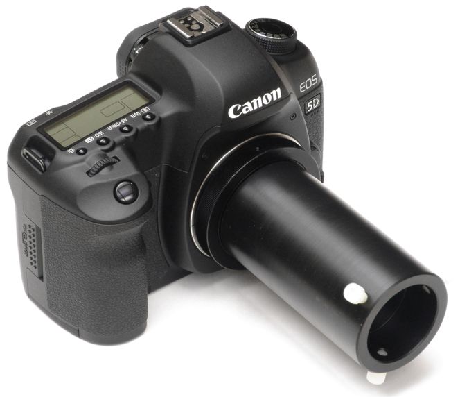 This is a Canon 5D Mark II digital SLR camera with the Olympus 38mm photoport adapter.
With an Olympus NFK 3.3X LD 125 photo eyepiece (or 2.5X), this projects a tightly cropped image to photograph the central
portion of the microscope's field of view in high resolution.
See additional photos of the Olympus 38mm dovetail adapter, including an add-on adapter to fit it to ISO 38mm trinoculars
on Nikon and Leica microscopes.
This is a Canon 5D Mark II digital SLR camera with the Olympus 38mm photoport adapter.
With an Olympus NFK 3.3X LD 125 photo eyepiece (or 2.5X), this projects a tightly cropped image to photograph the central
portion of the microscope's field of view in high resolution.
See additional photos of the Olympus 38mm dovetail adapter, including an add-on adapter to fit it to ISO 38mm trinoculars
on Nikon and Leica microscopes.
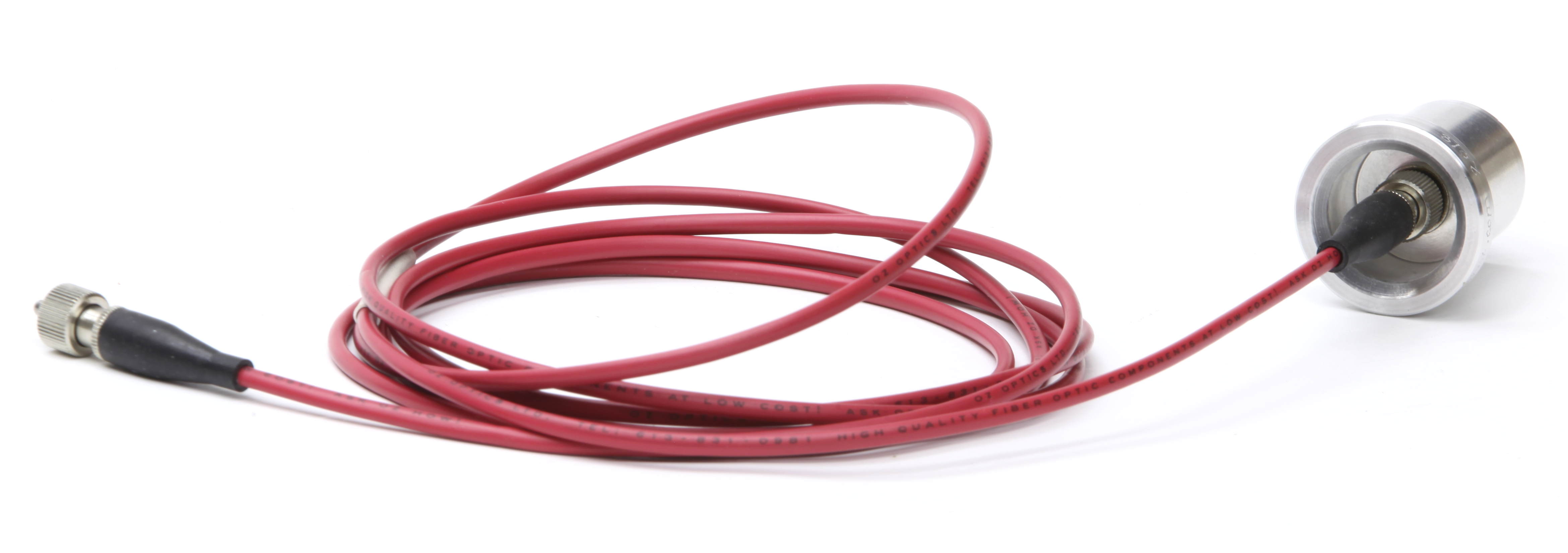 This photo shows a standard FC fiber optic patchcord (the red cord in the center of the photo, with free end on the left)
that couples to a microscope eyetube (23.2mm standard size in this specimen) via a custom adapter (seen at right).
The adapter subsitutes for an eyepiece in the microscope binocular to sample light from, or illuminate light onto, the microscopic subject.
This allows sampling light from a point in the microscopic image, and transmitting this sample through the patchcord.
The adapter is designed to place the fiber tip precisely in the focal plane of the microscope's eyetube.
Connecting the patchcord to a spectrometer provides a measurement of the spectrum emitted by the sampled area.
The area sampled is determined by the fiber core diameter used in the patchcord; patchcords are readily available with 100, 50, or 10 micron diameter fiber cores.
Since the microscope objective is working in reverse, the sampled spot size on the microscopic subject is reduced (minified) by the
magnification factor of the objective;
for example, a 10X objective would reduce a 100 micron illuminated fiber core diameter to a sampled spot of 10 microns on the subject.
Reversing the operation, one can insert light into the patchcord, and illuminate a tiny spot on the microscopic subject.
The adapter design also works with standard 30mm eyetubes (or other sizes),
either via a sleeve adapter, or by custom fabricating it in the 30mm diameter.
I also make these adapters to connect patchcords with SMA fiber optic fittings.
This photo shows a standard FC fiber optic patchcord (the red cord in the center of the photo, with free end on the left)
that couples to a microscope eyetube (23.2mm standard size in this specimen) via a custom adapter (seen at right).
The adapter subsitutes for an eyepiece in the microscope binocular to sample light from, or illuminate light onto, the microscopic subject.
This allows sampling light from a point in the microscopic image, and transmitting this sample through the patchcord.
The adapter is designed to place the fiber tip precisely in the focal plane of the microscope's eyetube.
Connecting the patchcord to a spectrometer provides a measurement of the spectrum emitted by the sampled area.
The area sampled is determined by the fiber core diameter used in the patchcord; patchcords are readily available with 100, 50, or 10 micron diameter fiber cores.
Since the microscope objective is working in reverse, the sampled spot size on the microscopic subject is reduced (minified) by the
magnification factor of the objective;
for example, a 10X objective would reduce a 100 micron illuminated fiber core diameter to a sampled spot of 10 microns on the subject.
Reversing the operation, one can insert light into the patchcord, and illuminate a tiny spot on the microscopic subject.
The adapter design also works with standard 30mm eyetubes (or other sizes),
either via a sleeve adapter, or by custom fabricating it in the 30mm diameter.
I also make these adapters to connect patchcords with SMA fiber optic fittings.
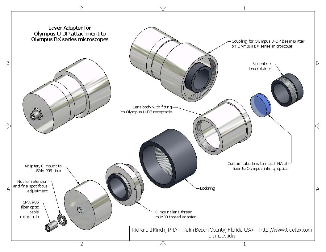 This adapter connects a laser source from a fiber optic patch cable (with SMA-905 fitting) to an Olympus BX microscope (with Olympus U-DP beamsplitter),
creating a microscopic laser spot focused on the specimen. The adapter afocalizes the end of the fiber, creating a collimated beam of laser light,
and inserts this beam into the Olympus microscope imaging path through the reflected path of the Olympus U-DP beamsplitter. The transmitted path through
the beamsplitter then accepts an Olympus binocular for live viewing (or trinocular with live-view camera). The collimated beam travels in reverse
to the microscope objective, which focuses the laser light onto the specimen. Thus we implement a spot epi-illumination system.
This adapter connects a laser source from a fiber optic patch cable (with SMA-905 fitting) to an Olympus BX microscope (with Olympus U-DP beamsplitter),
creating a microscopic laser spot focused on the specimen. The adapter afocalizes the end of the fiber, creating a collimated beam of laser light,
and inserts this beam into the Olympus microscope imaging path through the reflected path of the Olympus U-DP beamsplitter. The transmitted path through
the beamsplitter then accepts an Olympus binocular for live viewing (or trinocular with live-view camera). The collimated beam travels in reverse
to the microscope objective, which focuses the laser light onto the specimen. Thus we implement a spot epi-illumination system.
The size of the laser spot on the specimen, and the efficiency in transfer of laser power from the source to that spot,
are the design factors of this system.
These factors are in turn determined by the optics of the fiber, adapter lens, and Olympus infinity optics (UIS2) system.
The numerical aperture (NA) of the fiber determines the angle of spread of the laser light as it exits the fiber tip.
The afocalizing lens must have an equal or larger NA to capture all the laser energy.
Since the lens aperture is limited to the 20mm diameter infinity optical path of the Olympus microscope, this constraint on lens NA determines
the maximum focal length of the lens. Since longer focal lengths make for a smaller spot size, this limits how small the
spot can be with full power transfer. For a typical fiber NA of 0.22, this limits the focal length to about 45mm.
The Olympus BX infinity optics are based on a 180mm tube length, which thus fixes a 45mm/180mm = 0.25X enlargement of the
spot size from the fiber tip. This spot is then minified in the reverse path through the microscope objective's magnification,
so for example, a Olympus 50X objective would yield a spot magnification of 0.25X times 50X, or 12.5X. Thus a typical 50 micron fiber diameter
would be reduced by 12.5X to a 50 microns / 12.5X = 4 micron spot size. Patch cables with 10 micron fiber cores are available,
which would yield an 0.8 micron spot, which is about the diffraction limit for visible light.
Some power is inevitably lost in the reflections from the lens surfaces and the reverse path through the beamsplitter itself.
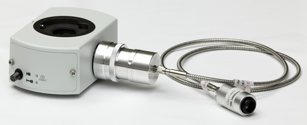 This is the assembled laser coupler, shown attached to the Olympus U-DP beamsplitter and an SMA-905 armored fiber patch cable.
The far end of the cable on the right is shown with a laser collimator from the laser manufacturer
(laserglow.com); this couples the laser source beam efficiently into the fiber.
Additional photos and details on my laser coupler for the Olympus BX series microscopes are here.
This is the assembled laser coupler, shown attached to the Olympus U-DP beamsplitter and an SMA-905 armored fiber patch cable.
The far end of the cable on the right is shown with a laser collimator from the laser manufacturer
(laserglow.com); this couples the laser source beam efficiently into the fiber.
Additional photos and details on my laser coupler for the Olympus BX series microscopes are here.
Since the adapter assembles with a C-mount lens fitting, it happens to work in the other direction as a C-mount camera adapter for the Olympus BX.
With a 50mm lens it provides an effective 0.27X reduction yielding an 6mm image circle, suitable for 1/3" or 1/4" format camera sensors.
Likewise, it will reassemble with an Olympus U-DP1XC adapter for a 1X laser adapter with NA=0.05.
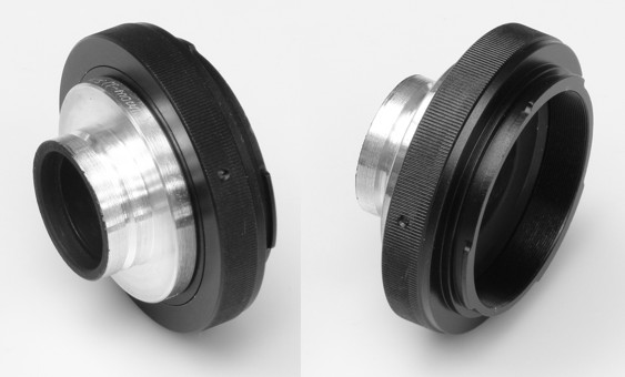 This custom item adapts a Zeiss 30mm photoport to a Canon EF-mount digital SLR via a stock T-mount adapter.
This also adapts Nikon or Olympus digital SLRs by changing the T-mount adapter.
This Zeiss 30mm photoport standard is used on many newer microscopes, and the adapter is compatible with the following:
This custom item adapts a Zeiss 30mm photoport to a Canon EF-mount digital SLR via a stock T-mount adapter.
This also adapts Nikon or Olympus digital SLRs by changing the T-mount adapter.
This Zeiss 30mm photoport standard is used on many newer microscopes, and the adapter is compatible with the following:
- Zeiss Axiolab
- Zeiss Axiophot 2
- Zeiss Axioplan 2
- Zeiss Axioskop (2, 20, 40 variant, 40 A Pol, 40 FL, 40 Pol, 50)
- Zeiss Axiostar (including plus and vario)
- Zeiss Axiotech
- Zeiss Axiovert (100, 135, 135M, 200, IM)
- Zeiss Palm (CombiSystem, MicroBeam, and MicroTweezers)
- Zeiss Stemi (2000 C, SV-6, and SV-11)
|
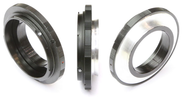 This custom item adapts the Zeiss 47mm photoport to a Canon EF-mount digital SLR.
This Zeiss photoport was used on many older microscopes, and the adapter is compatible with the following:
This custom item adapts the Zeiss 47mm photoport to a Canon EF-mount digital SLR.
This Zeiss photoport was used on many older microscopes, and the adapter is compatible with the following:
- Zeiss Axiomat (*)
- Zeiss Axioplan 1
- Zeiss Axiophot
- Zeiss Axioskop 1
- Zeiss Axiotron
- Zeiss Axiotron 2
- Zeiss Axioskop 40
- Zeiss Axiovert 10, 35, 35M, 405M
- Zeiss Photomicroscope 2, 3 (*)
- Zeiss UEM (*)
- Zeiss Ultraphot IIIB (*)
- Zeiss Universal (*)
(*) = longer version with extended tube length.
|
Scope TV adapter
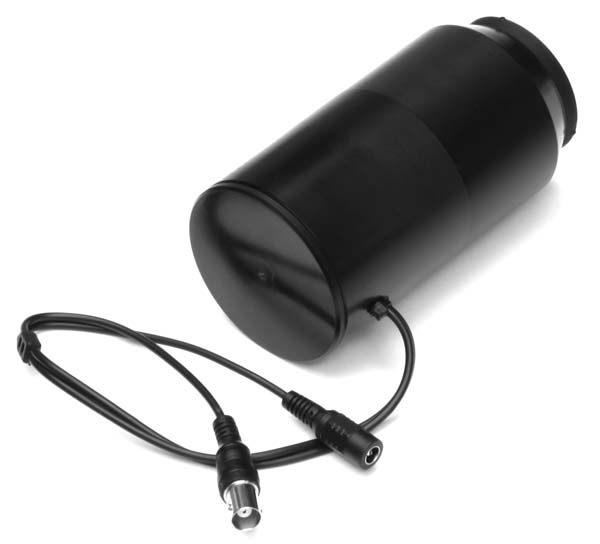 This is a custom-made TV camera which attaches to a rifle scope. The adapter body is 2.5 inches diameter by 5 inches long.
It ends in a three-point kinematic attachment using setscrews to the scope eyepiece.
Inside the adapter body is a Sony standard-definition PC board camera with an afocalizing lens aligned with the exit pupil of the
scope. The focal length is chosen to crop the scope's angular field of view to the rectangular video image.
The PC board camera provides two connectors, which are 12 volts DC power input and a BNC connector for composite video out.
This is a custom-made TV camera which attaches to a rifle scope. The adapter body is 2.5 inches diameter by 5 inches long.
It ends in a three-point kinematic attachment using setscrews to the scope eyepiece.
Inside the adapter body is a Sony standard-definition PC board camera with an afocalizing lens aligned with the exit pupil of the
scope. The focal length is chosen to crop the scope's angular field of view to the rectangular video image.
The PC board camera provides two connectors, which are 12 volts DC power input and a BNC connector for composite video out.
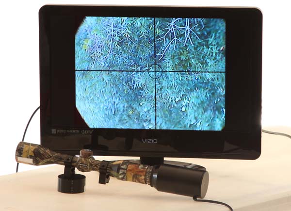 Here is the TV camera adapter mounted on the scope and pointed outdoors into a distant tree.
The video output is shown on a Vizio HDTV monitor using the composite video input for a standard-definition TV signal.
This adapter could also be fitted with a HD webcam to provide an 720p or 1080p HD video from the scope view via USB to a PC.
Here is the TV camera adapter mounted on the scope and pointed outdoors into a distant tree.
The video output is shown on a Vizio HDTV monitor using the composite video input for a standard-definition TV signal.
This adapter could also be fitted with a HD webcam to provide an 720p or 1080p HD video from the scope view via USB to a PC.
Understanding Cropping
In adapting cameras to instruments, "cropping" is always an issue, because the shape or aspect ratio of the
field of view of the instrument rarely matches the field of view of the camera. Some compromised
choice must be made of how to scale and overlay one field against the other. This choice of
geometry is called the "crop", and is fixed by the optical scaling by the adapter
of the instrument field onto the digital camera sensor.
The cropping describes how the circular shape of the microscope's field of
view is fitted to the rectangular shape of the camera's field of view. Since
these shapes do not match, the fields cannot be scaled and overlaid without
leaving some of one or the other (or both) fields unused. The type of cropping
is chosen based on the goals of the application. In choosing the cropping, one
must evaluate whether it is better to not use part of the microscope field,
versus not using part of the camera field, or some combination of the two.
Depending on the application, this choice may be simply a matter of visual style,
or it may be dictated by requirements such as having to see all of the
microscope field (which dictates an inscribed crop) or having to use all of the
camera field (which dictates an outscribed crop). On some adaptations, the
crop is fixed by the adapter; on others a zoom lens on the camera is
incorporated, so the user can change the crop by zooming between
wide-angle and telephoto settings.
 Inscribed cropping: The circular microscope field of view "inscribes" the
rectangular camera field of view. This is the most commonly used crop,
because it "looks" like a traditional microscope film photograph, and good
digital cameras are able to capture all of the resolution of the image at this
scale. While all of the microscope's field of view is captured in the photograph,
the left and right sides of the photograph are unused area. With digital
photography, the unused areas of the photograph can be filled-in during
post-processing to be white or transparent instead of just black. Geometrically
speaking, to establish inscribed cropping, the optics of the adapter scale the
vertical aspect of the camera field to the diameter of the circular microscope
field. Sometimes the scaling of the circular field may be deliberately shrunk to
somewhat smaller than the vertical aspect, to allow for manufacturing
tolerances in the optical and mechanical elements.
This photo (also shown above
for the adapters for American Optical microscopes) shows an example of a digital
camera on a microscope with inscribed cropping of the microscope field of view
displayed on the camera's LCD viewer.
Inscribed cropping: The circular microscope field of view "inscribes" the
rectangular camera field of view. This is the most commonly used crop,
because it "looks" like a traditional microscope film photograph, and good
digital cameras are able to capture all of the resolution of the image at this
scale. While all of the microscope's field of view is captured in the photograph,
the left and right sides of the photograph are unused area. With digital
photography, the unused areas of the photograph can be filled-in during
post-processing to be white or transparent instead of just black. Geometrically
speaking, to establish inscribed cropping, the optics of the adapter scale the
vertical aspect of the camera field to the diameter of the circular microscope
field. Sometimes the scaling of the circular field may be deliberately shrunk to
somewhat smaller than the vertical aspect, to allow for manufacturing
tolerances in the optical and mechanical elements.
This photo (also shown above
for the adapters for American Optical microscopes) shows an example of a digital
camera on a microscope with inscribed cropping of the microscope field of view
displayed on the camera's LCD viewer.
 Outscribed cropping: The circular microscope field of view "outscribes" the
rectangular camera field of view. This results in photographs which are
completely "lit" without any black, unused areas, but the edges of the
microscope field of view are not recorded in the photograph.
Outscribed cropping: The circular microscope field of view "outscribes" the
rectangular camera field of view. This results in photographs which are
completely "lit" without any black, unused areas, but the edges of the
microscope field of view are not recorded in the photograph.
See these same descriptions and diagrams of cropping on a
single-page drawing [79 KB PDF file, 1 page].
Kinematic Principles of Design
I am often asked about designs for optical assemblies and how lens elements can be
inserted into them. Herewith is my universal list of methods for lens mounting:
- Threaded retaining ring against a shoulder, or against each other.
- Wire retaining spring or rubber O-ring in a V-groove.
- Flat spring against an outside diameter.
- Burnishing (spinning).
- Press-fit retaining ring.
- Punch-deformed projecting ears.
- Edge-on setscrews or setsprings.
- Three grooved rods at 120 degrees.
- Capturing groove or recess, assembled from segmented or split parts. Assembly by gluing, screwing, or conjugate threading.
- Rigid or RTV cementing. A special trough groove catches excess cement.
In addition, a helical spring can extend the length of the lens for
shock absorption against shoulders.
Proper optical assemblies embody kinematic design principles.
The term kinematic in this context means that the mechanism provides minimal mechanical constraints
to locate the components relative to each other. Since location in space involves six degrees of freedom
(three of translation and three of rotation), the minimum number of point contacts to fix two bodies
is six. For every allowance of motion along a degree of freedom, one less point contact is required.
A converse statement of this principle is that no component is redundantly constrained.
In short, the assembly is minimally constrained, or non-overconstrained.
One consequence of the kinematic principle is that precise designs should involve points of contact rather than
areas of contact. Precision is not perfection.
Rigid parts are never geometrically perfect, and forcing areas (instead of points) to conjugate will
produce unpredictable forces which degrade mechanical precision.
In summary, the kinematic principles impose the following practices [Jacobs]:
- Light, well-controlled forces should fasten points of contact, such that
the elastic material property is not significantly deformed. While promoting precision,
this principle also can yield designs which are delicate and insufficiently robust for
rugged applications.
- Relative positioning of bodies should not depend on the accuracy of the mechanical contacts.
This allows parts to wear normally without degrading performance.
- Differential designs amplify precision. For example, a differential screw
mechanism provides a predictable adjustment more precise than the precision of the screw threads themselves.
- Kinematic designs can amplify imprecision. For example, using points of contact as bearings
can result in a sensitivity to surface irregularities.
Precision bearings consequently involve anti-kinematic principles, spreading forces over large
areas which provide stability under heavy loads.
- Kinematic designs can amplify wear.
Having smaller areas in contact increase pressure,
introducing problems of lubrication and wear.
-
The same mechanical principle may be implemented with opposite results in kinematic trade-offs.
For example, a C-clamp and a micrometer are indentical devices in mechanical principle, but
the former is made to apply large forces with minimal precision, while the latter applies minimal
force to measure with high precision.
Links for Digital Photomicrography
- My drawing of frame sizes [PDF file] for 35mm film versus the Canon 400D digital camera versus a microscope 10X WF eyepiece field of view.
This is helpful in analyzing how various imaging sources and detectors will result in cropped images.
The diagrams show the original circular or rectangular field with inscribed and outscribed rectangles or circles.
Printing this document at 1:1 scale will be true to the actual sizes, making it usable as a physical test pattern.
- Gregor Overney's
"Introduction to Digital Photomicrography".
- Steve Durr's Introduction to Photomicrography.
- Paul James' Mounting digicams with zoom lenses over the microscope.
- Paul James' High Eyepoint Oculars and the Digicam.
- Peter Evennett's The New Photomicrography [PDF document].
- Micrographia's tutorials on optical designs for microscopy.
- Barry Carter's Afocal Photography.
- The Molecular Expressions Web site.
- Modern Microscopy Web site.
See the article on equivalency of digital camera photomicroscopy to Polaroid 4x5 film,
"Array Size Needed to Replace Photomicrographs on Film", by Ted Clarke.
Also his article, "Fitting a Student Microscope with a Consumer Digital Camera" [PDF document].
- Ching-Kuang Shene's discussion of digital camera lens threads and adapters, particularly in regard
to the Nikon Coolpix 4500.
Also his page Nikon Coolpix 5700 adapters, which illustrates some potential problems
with cameras having extending-turret lenses.
Both of these are parts of his digital camera page.
- Giorgio Carboni's Pictures and Movies with the Microscope.
- Edmund Industrial Optics.
They offer universal [sic] digital camera microscope couplers, which
are essentially large eyepieces that replace your 23mm or 30mm standard microscope eyepiece. Since this approach reimplements the eyepiece optics, the expense runs
about $500 to $700 for a complete adapter assembly, which is about 4 times the cost of simpler adapters that use the existing eyepiece.
Edmund seems to disclaim any performance for their adapters by stating,
"none of the above cameras have been tested, and significant vignetting may occur at lower zoom settings."
Also useful for making your own adapters are Edmund's T-mount components.
- Nikon USA paper, Mounting a Coolpix 5000 onto a Microscope [PDF document].
- Raynox camera adapter page.
A Japanese manufacturer of step-up/step-down rings and turret-lens adapter tubes.
The table provides a reference for the native filter thread size of many cameras.
- The Japanese firm go4dc.com offers attachments to provide filter threads on
various digital cameras that don't otherwise have them. Also offers filter thread step-up and step-down rings.
Requires Paypal prepayment, then mails you the item from Hong Kong!
- Filter-thread and bayonet-mount adapters are available from online merchants like Adorama and
B&H Photo.
- Optical Society of America. Publishes
the Handbook of Optics and
the Optical Engineer's Desk Reference.
- LightMachinery.com provides free optical calculations and design tools online,
including an exact ray trace lens designer.
- William-Jan Markerink's list of camera mounts (Dutch).
Stephen Westin (at my alma mater, no less!)
has a version in English.
- Navitar's page on Optical characteristics of [C-mount] video lenses.
- R. N. Clark's notes on the resolution, dynamic range,
dynamic range, focal length, and f-number of the human eye.
- Cass Sackett's lecture notes [PDF file] on the optics of the
human eye.
- Links on optics at www.opticsnotes.com.
- Ian Walker's review of the Zeiss Axiostar universal digital camera adapter.
This item appears to replace the eyepiece with an 0.75x negative lens, in addition to the
mechanical adaptation of the 30mm eyepiece tube to 52mm filter thread.
A telescoping tube with screw lock allows adjustment of the vertex distance.
- Micscape Magazine (UK).
- Lensmate makes filter thread adapters for various Canon Powershot cameras.
- Karen Nakamura on Canon EF mount lenses.
She asserts most EF lenses provide 58mm filter threads, with 52mm on some cheaper lenses, 78mm on most professional lenses, and 72mm on
some older lenses.
- Alan Wood documents the Olympus OM series of film cameras (1972-2003), for which Olympus produced adapters for fitting to Olympus microscopes,
at his Olympus OM System Page.
- Paul van Walree has an excellent Web page on vignetting in the context of ordinary photography.
Indeed, while he demurely claims to be "not professionally involved", his pages on optics give general
descriptions and photographic examples of optical aberrations, errors, and other effects which outdo the leading textbooks.
- Microscope enthusiast and amateur microscopist P. S. Neely maintains a detailed page on
eyepieces as part of his
historical collection of AO (American Optical) Spencer Microscope Manuals and Catalogs.
He supplies technical specifications on an extensive list of eyepieces from
Zeiss, Reichert, Leitz, A O Spencer, Bausch & Lomb, C Baker, CTS, Beck,
Wild Heerbrugg, PZO, and Olympus.
- Rolyn Optics provides a 4-page sheet of the most commonly used optical formulas.
Also a page with properties of common optical materials.
- Engineering standards for mechanical, optical, and electrical interfacing to microscopes include:
- DIN standard for 23.2mm and 30mm eyepiece barrels.
(I believe these are superseded by the ISO standards below.)
- ISO 10937:2000, "Optics and optical instruments -- Microscopes -- Diameter of interchangeable eyepieces".
Google search for the title.
Available at ansi.org.
- ISO 9345-1:1996, "Optics and optical instruments -- Microscopes -- Imaging distances related to mechanical reference planes -- Part 1: Tube length 160 mm".
Google search for the title.
Available at ansi.org.
- ISO 9345-2:2003, "Optics and optical instruments - Microscopes - Imaging distances related to mechanical reference planes - Part 2: Infinity-corrected optical systems".
Google search for the title.
Available at ansi.org.
- JIS B 7143:1977, "Engagement between microscope eyepiece and eyepiece sleeves".
Google search for the title.
Available at ansi.org.
- ISO 10935:1996, "Optics and optical instruments -- Microscopes -- Interfacing connection type C" (that is, C-mount).
Google search for the title.
Available at ansi.org.
- ISO 10939:1998, "Ophthalmic instruments -- Slit-lamp microscopes".
Google search for the title.
Available at ansi.org.
- ISO 11882:1997, "Optics and optical instruments -- Microscopes -- Interfacing connection for 35 mm SLR photo cameras (T-thread adaptation)" (that is, T-mount).
Google search for the title.
Available at ansi.org.
- ISO 10330:2002, "Photography--Synchronizers, ignition circuits and connectors for cameras and photoflash units -- Electrical characteristics and test methods".
Google search for the title.
Available at iso.org.
-
The "hot shoe" attachment for camera flash accessories is specified by
ISO 518,
"Photography -- Camera accessory shoes, with and without electrical contacts, for photoflash lamps and electronic photoflash units -- Specification".
-
The "PC sync" connector for camera flash synchronization is specified by
ISO 519,
"Photography -- Hand-held cameras -- Flash-connector dimensions".
This document is actually an anti-standard, since it disclaims that,
"To accommodate some freedom in design and use of materials, the dimensions
of the cone-shaped tip of the plug pin and the protruding length of
socket insulation and outside contact are not specified. Both influence
the overall length of electrical coupling, however, and they should not
be excessively long."
- Lots of stock step-up and step-down rings, and conversion lens adapter tubes, are to be found for sale at camerafilters.com.
- Lens fungus: Read my developing essay about lens fungus, the bane of optical engineering.
- Digital upgrades for ophthalmological instruments: See my summary list of digital camera upgrades for ophthalmological instruments such
as retinal cameras and photo slit lamps.
- Micro-Manager Laboratory Control Software:
This free, open-source software (http://www.micro-manager.org/)
operates computer-controlled microscopy apparatus such as tethered cameras and motorized stages,
working with ImageJ for image processing.
Have a comment or question about my digital camera microscope adapter projects? About digital photomicrography?
Want to purchase a custom-made adapter?
Email me at:
kinch@truetex.com
Richard J. Kinch
Back to Machine Shop page
Back to Home page
Copyright 2002, 2003, 2004, 2005, 2006, 2007, 2008, 2009, 2010, 2011, 2012, 2013, 2014, 2015, 2016, 2018 Richard J Kinch
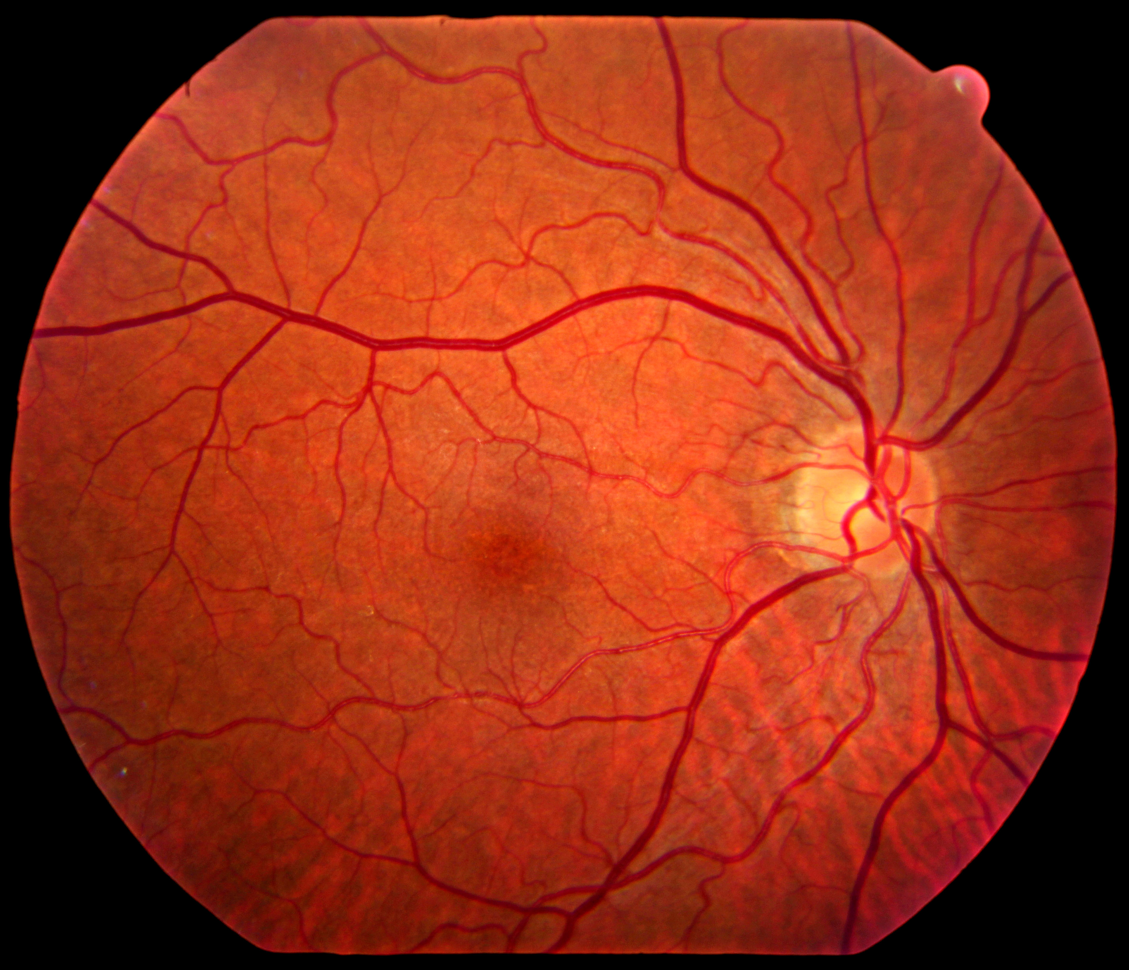
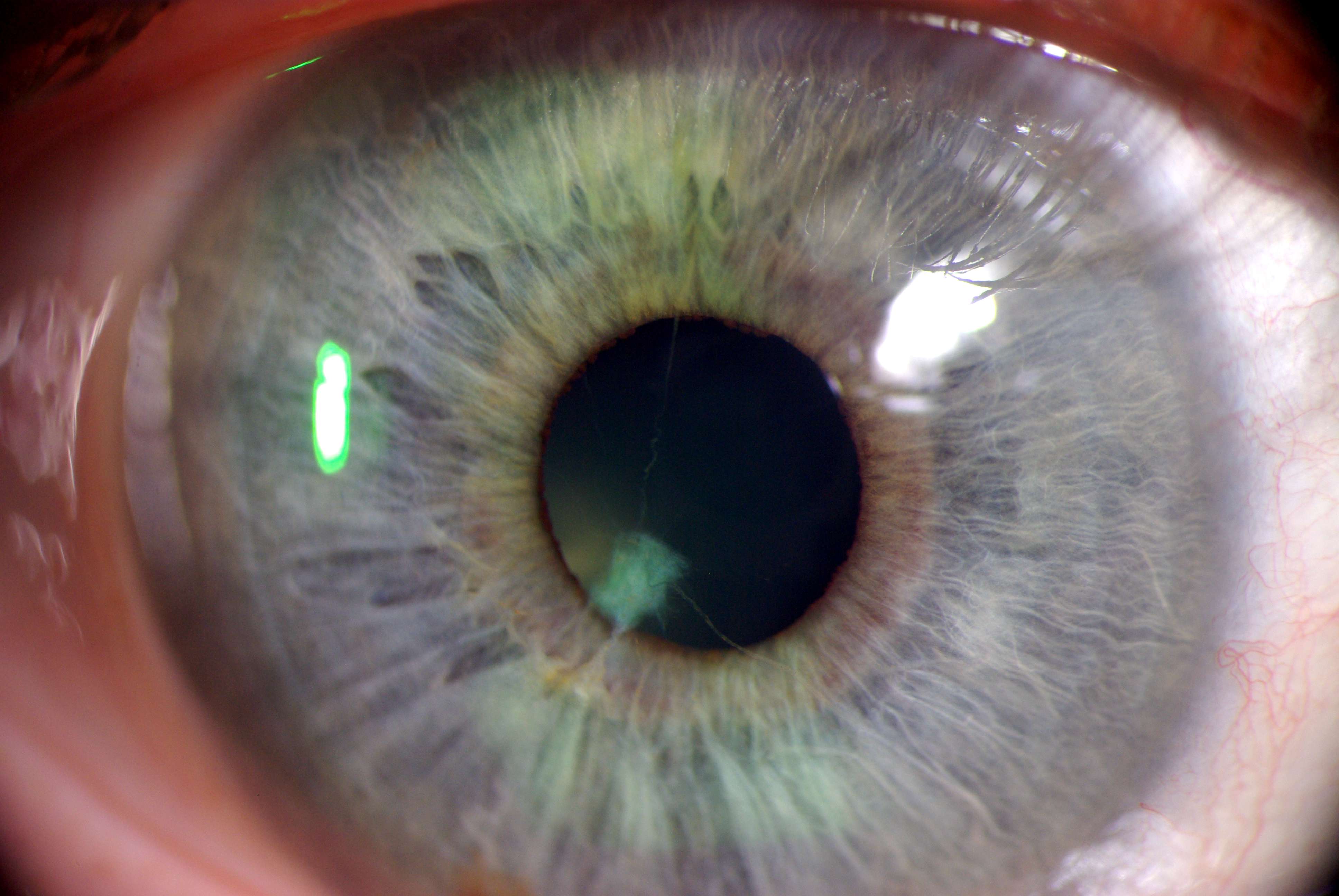
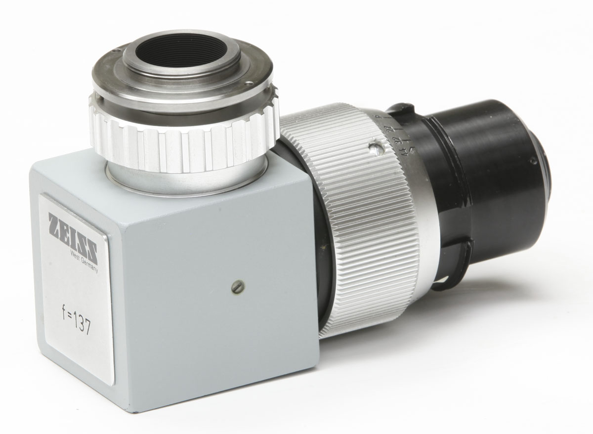
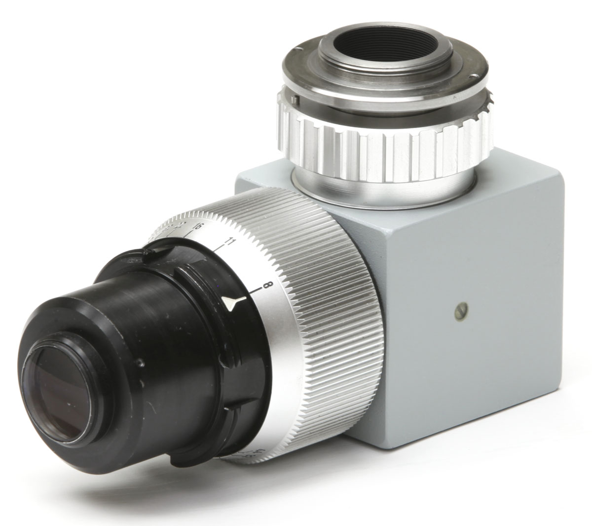
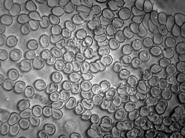
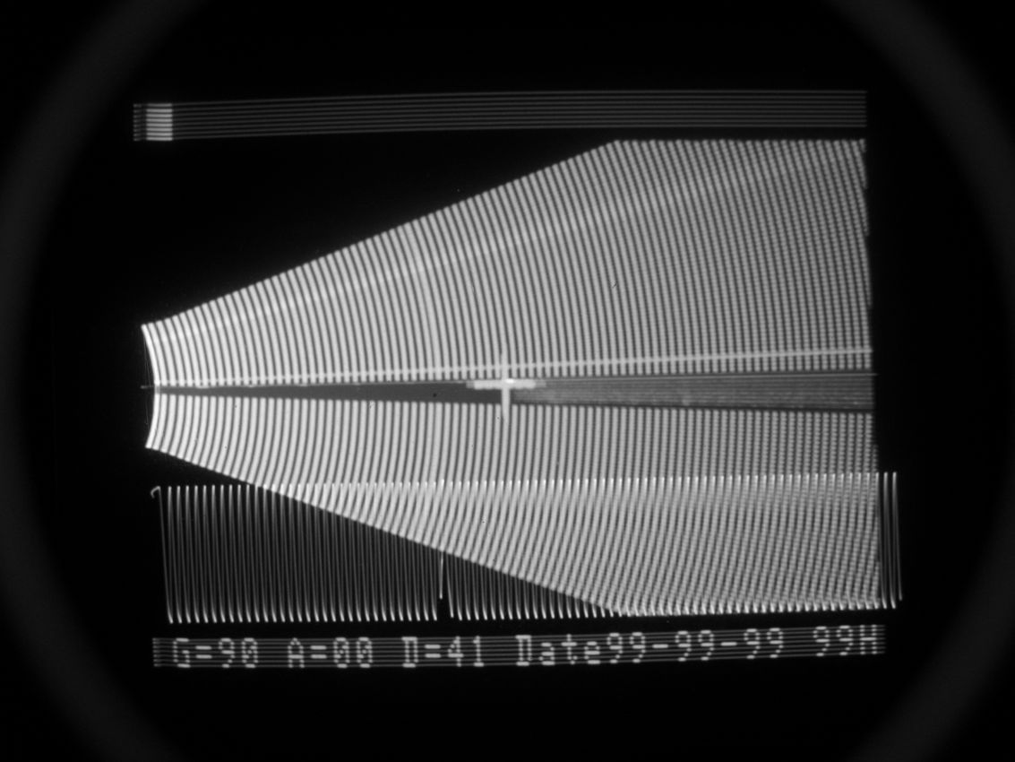